GNG, 1000W 48V BB-drive, $400

155rpm is far to much. I calculated with 120 no load, my setup gets 115rpm and still runs to fast. Next time i'll calc with 100rpm.

It almost needs another stage reduction, or a much larger pulley. If you are happy to not pedal along with it, then it is probably ok.

I wonder if you can run it on, say, 24v instead?

A reduction ratio of 13T to 76T with a 8mm chain would fit well I guess. Driving it with 36Volts would also be ok I guess, it would be a little less noisy also.
 
adrian_sm said:
No-load cadence of 155rpm sounds high. But I guess once it loads up this puts peak power out at more normal cadence.
So 48V x 3.6A = 170w up to the first stage. What is the no-load current including the second stage?
It's high, but considering peak power is at around half no-load I'm not too worried. A bigger chainring or dual freewheel and a fixed driver with smaller chain is possible.

So, @48V the motor alone consumes 115W. Not bad for 3,500RPM. The 1st stage adds another 60W. The belt noticeably warms up. It kinks significantly due to the tensioner, which is required. The wraparound is 9 or 10t.

The next stage shouldn't add much. Can only find out once fitted.

Will take pictures tomorrow.
 
Looking forward to it.

full-throttle said:
So, @48V the motor alone consumes 115W. Not bad for 3,500RPM. The 1st stage adds another 60W.

Just as a comparison, my Crystalyte 408 direct drive hub motor @ 82V draws 1.4Amps no load = 114w
My friction drive's motor no load draw is ~2.3A @ 21v = 48W, plus another ~60w when the drive is fully engaged with the tire. So back up around 110W.
 
That tensioner sprocket is in fact a standard derailleur pulley. if it gives you any problems, you can easily buy or use an existing derailleur pulley to replace it. You can even probably use one with a different tooth count.

I am thinking of replacing mine with something made of medal instead of plastic so that it will last longer. Mine is 10 tooth like yours. I will probably get a 11 tooth one since that seems to be the smallest one I can find that is made of an alloy metal and doesn't cost a fortune. (not sure how a simple medal gear can cost so dam much)

I'm not entirely sure what you mean by "kinking" but mine did something similar (I think?) where the chain would sometimes stick to the motor sprocket on the exit side too long and jam the chain. (happened on the end of the motor sprocket where the chain exits towards the chain tensioner pulley).

I lubricated the chain with a wax based lubricant and now it runs perfectly smooth and doesn't kink or make any other unusual noises. Perhaps your kinking issues can be solved by chain lubricant?

Also if your Bottom Bracket isn't wide enough, you can get a bottom bracket spacer ring (they are dirt cheap) and put it on one side so that the motor bracket doesn't have to be squeezed onto the smaller bottom bracket. They have spacer rings of many different sizes so you can probably get one to the exact size you need. a 1mm spacer seems to be what you need if your BB is 67mm and the BB the bracket is for is 68.

I used roughly 3-4mm worth of BB spacer rings on the right side of my BB, but that's mostly to get my motor bracket lined up straight with the chain wheel due to the width of the rear forks at the mount point on the other end of the motor bracket being wider then the BB.

Yours mounts differently thus you probably won't have that issue. The under the forks type mid-drive kits I would recommend you stay away from unless you have a suspension bike that has the pivot in a place where the front mounted ones wouldn't work. They are real finicky on most bikes and I had to take mine off the suspension bike because the rear forks are just too wide and I can't get the motor bracket lined up since I don't have enough exposed threading left on the left side BB cup so that I could use enough spacer rings to fix the alignment. :( (the lockring is the important part I must ensure can stay on, thus the need for exposed threading on the left side cup)

But now that it's back on my road bike, the BB cup on the left side has exactly enough threading for the lockring and thus my additional 1.8mm ring on top of the 3mm rings I had before makes it pretty much perfect. :D
 
Hmm, I am very interested in this kit. I would like to see how it stacks up against my MAC mid drive! My brother wants something a little more compact and does not need the power I wish to have so this might suit him really well!
 
The first 4 photos are from 4 sides of the motor assembly
The next one with the guard removed shows the belt tensioner
Next one shows jackshaft mounting
Then the chainring assembly (30mm wide)
And the last 2 the freewheel adaptor. Solid steel, easy to find spares. 4-bolt 64mm bcd - standard inner ring if I recall correctly.
 
Wow! That actually looks like a solid unit. Now if only someone could confirm the specs of the motor (max and min voltage, max and min wattage). If these can sustain 48v and 1200w, I'm buying a few.

Dredd
 
Nice - very nice, especially that freewheel adaptor with the bearing, should solve some of those issues that plagued the cyclone setup.

Can I get you to measure (when you get the chance) the outside diameter of the bit that goes around the BB (or the distance from the inside to outside).
 
Oh so the tensioner for the belt, not the one for the chain side of the drive. I guess the one way of solving that is to find a shorter belt so that the tensioner isn't required?
 
Hmmmm...

I don't like the look of that idler pulley set-up. No wonder it's so inefficient... With a 14t driver pulley, 80t driven and short C.D., I can see why it's needed, though....
 
Yeah, without it the wrap-around would 5~6t.

How would you do it Miles? Cantilever arm?
At the moment there are 2x 5mm bearings and 5mm gap in the middle.
 
The main problem is the small idler pulley diameter and large wrap around it, that's necessary. I think it's a compromise too far.

Lot's of good things about the kit, though: support bearing for chainrings, easy to replace/upgrade the crank freewheel etc.
 
Miles said:
Hmmmm...

I don't like the look of that idler pulley set-up. No wonder it's so inefficient... With a 14t driver pulley, 80t driven and short C.D., I can see why it's needed, though....

Looks like the original design did not have the idler. The photos on their website still don't show it. So I assume it was a late addition.
Source: http://www.gngebike.com/450wbrushless.htm
7423489584_066cb0ec26_o.jpg


Then it would have been a compromise to try and use more drive teeth while keeping the existing centre distances, and using available belt lengths. Pity.
 
adrian_sm said:
Then it would have been a compromise based on keeping the existing centre distance, and the available belt lengths. Pity.
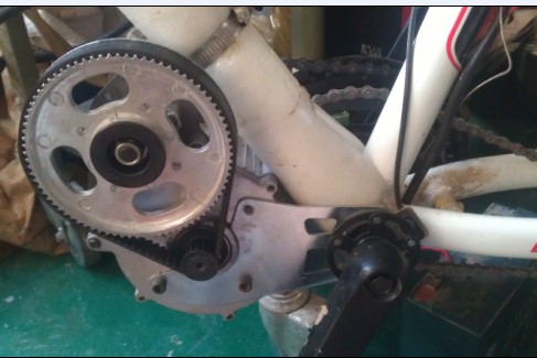
I guess they had to add it because they had problems with ratcheting on the driver pulley....

Edit: Sorry Adrian, beat you to your edit :)
 
full-throttle said:
adrian_sm said:
So I assume it was a late addition.
Definitely. The sheet-metal still has the slotted holes for tensioning. Guess I could easily modify it with a larger dia pulley..

Yep. By ratcheting do you mean skipping/jumping teeth? That is more of an issue for a no idler system of belt stretch/centre distance movement isn't it.

I sort of assumed they would have just started ripping teeth off. Not sure what the ideal number of teeth are (been a while since I designed a belt drive). But as the number of drive teeth increases, most of the load is still taken by the first XXX teeth engaged, just not sure how many you need before you don't get any benefit from more teeth. But since 18teeth seems the minimum stock pulley size, 9 would seem a fair number. Very unscientific, but hey.

Anyway hurry up Dmitrii I want some videos of you ripping up the trails on this thing.
 
Back
Top