Help with ping bms

auraslip

10 MW
Joined
Mar 5, 2010
Messages
3,535
Riding home from the store today my bike lost power with in site of my house. I've been having trouble with my shitty crimp jobs on some andersons, so I just took it home.

I plugged it in and all the cells were growing red, but the battery still was not putting out power.
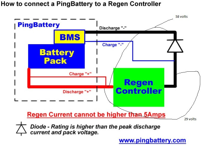
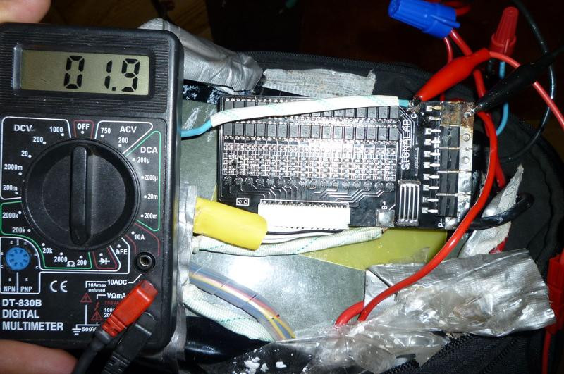
For some reason I thought maybe it was the diode, and it appears I was correct about this. The voltage at the main pack was 29, but before the diode it was a normal 58. So I think great, I don't need a diode. I'll just turn my regen braking system off. I wired the two thick red and black cables to the controller, and the thin blue and red to a new charger input as per http://www.pingbattery.com/usrguide/Wiring%20Guide%20V2.5.pdf

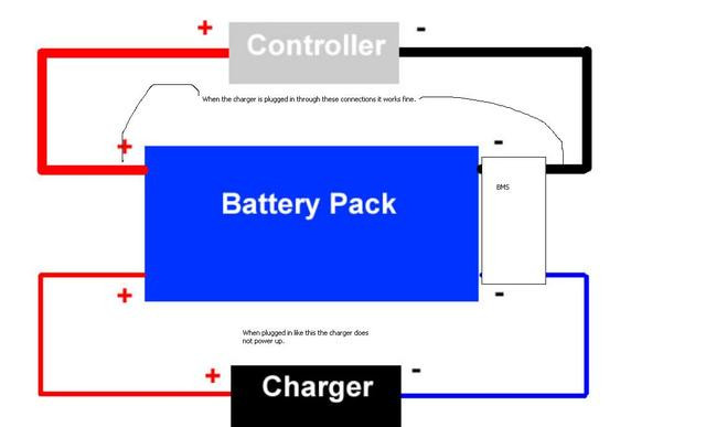
The bike works. Maybe even a lil' peppier for lack of the diode. However now the charger won't work, when I plug it in to the new connection. The charger does charge the battery when I briefly plugged it into the controller connection as a test.

What's going on here? Why did the diode fail in the first place?

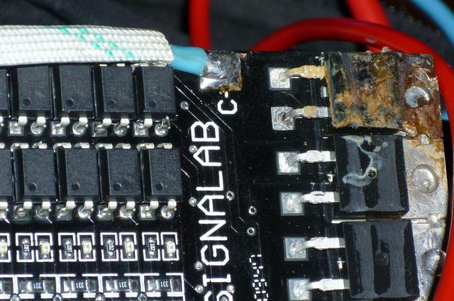
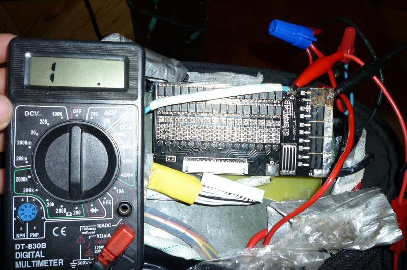
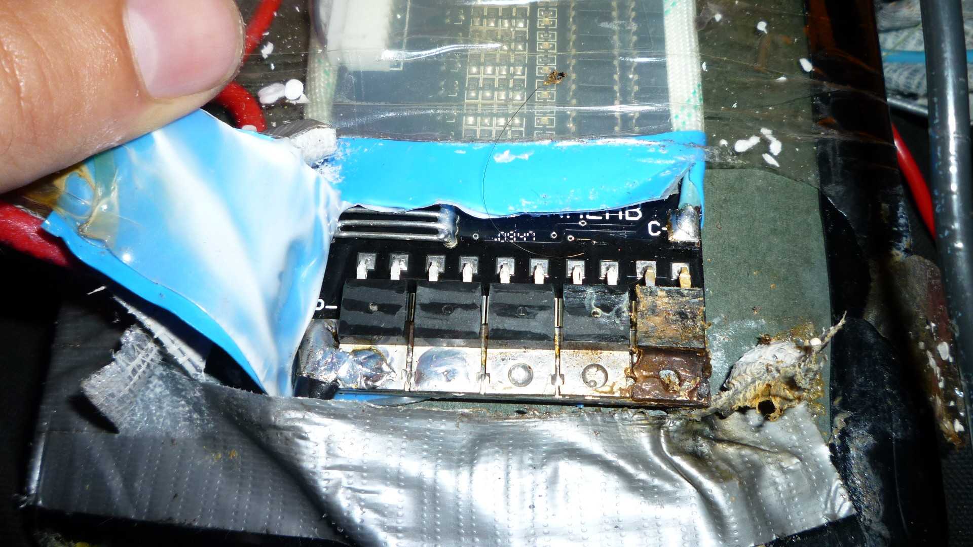
Also for your judgment is a picture of the bms. The far right mosfet (I think...) Is covered with burned up duct tape. I measured the voltage between each leg of the 5 mosfets. They all read ~14 except the far right one. Could this be a cause?
uxxas.jpg
 
The diode was to allow you do have regen braking, but not send the power into the battery?
 
http://www.pingbattery.com/usrguide/Wiring%20Guide%20V2.5.pdf

You can deduce how it was wired from this.

The diode allowed me to regen brake without sending power to directly through the battery. The diode allowed power to be drawn from the battery to the controller, but not vice versa. The power generated from braking when return to the battery via the bms charging circuit. This way protects from over voltage.


Dnmun - as long as the cells don't become unbalanced shouldn't the battery remain at a safe voltage? Why shouldn't their have been a diode?
 
TzHIZ.jpg


Dnmun i saw your thread where you talked with doctor bass about replacing the charging mosfet. I imagine this is the problem as that mosfet looks burnt. Do you know how I could test it with a volt meter? I could get the mosfet over night delivery and have it fixed so I don't miss school on friday.

2ChW3.jpg


here is the picture again. I have a huge lcd screen, so sometimes I forget i need to resize for most people to see all of the image.
 
not sure how that charging FET would burn up.

you can see if it is turned on by measuring the voltage on the gate leg. that should be about 10-12V.

gate leg is on the left side, closest to the edge of the board.
 
Between the gate and drain (positive on the gate, negative on the metal part opposite side of gate that the negative battery cable is soldered too) read ~6v.

The plastic melted off. This allowed the mosfet to come in contact with the fabric of the bag it was in. Perhaps a static charge built up and shocked it?
 
the plastic melted because your charging FET got hot, i assume during regen. you said the pack did take charge initially.

if you can get the pack to charge, you should turn off the regen, leave the diode out of the drain circuit back to the battery. since there aren't pictures and i am not there to examine the connections, you will have to do that yourself.
 
VDqik.jpg


Does this make sense? What connections would you like pictures of? I've tested them all for continuity. The the small blue negative cable attached to the BMS at -c is the only one that doesn't give a reading.
 
the plastic melted because your charging FET got hot, i assume during regen.

It's weird though, because the FETs would always get hot while riding. Where I live is pretty flat and most of my riding is country side, so I don't have to stop at every block.
 
to test the charging FET, disconnect the sense wire plug from the BMS so the gate voltage on the charging FET goes to zero.

then measure the resistance between the source leg and the drain which is the tab. or you can measure between the C- lead and black wire running from the BMS to the pack. make sure you disconnect the charger when you measure the resistance. should be infinite.

plug the sense wire back in and the gate voltage should jump back up to 10V and then the resistance between the C- lead and black wire should go to zero.

it should charge if the mosfet turns on.
 
Notice anything funny about the source leg of the mosfet? It's not making a good connection!
scn1Z.jpg

One quick solder job later everything seems normal!
aJ2GQ.jpg

0CxEY.jpg


It's charging up fine now. I just wonder how is it that both the diode and this came unsoldered at once...
 
looks good, i checked on a v 2.5 signalab and the gate voltage is 6.3 like you said. it is 12 or so on the v1, the source drain junction is what they call a body diode which conducts in one direction and not in the other. the source leg usually is in a bed of solder on the backside, but a cold solder joint and a lotta regen current could get it hot fast. maybe solder a fin or some kinda way to dispose of the heat onto the tab, get it out into the air if you wanna use the diode and regen.

but the diode may lose more energy than you recover from regen. .4Vx25A average current=10 watts power loss avg.
 
Maybe I'm imagining it, but my bike feels faster with out the diode :/
I know your gonna hate it, but I run with out the diode and regen still on. I figure since anytime I leave my house I have to ride 3 miles straight and flat with no stopping I'll never get a chance to overcharge the battery. Also lack of hills here in texas.

I'm surprised at how cool the BMS is now with out regen. To me it seems strange how such little amount of braking could heat up the fets so hot.
 
Back
Top