steveo said:
Love the motormounts.. hahaha... definatly a solid mount by the looks of it..
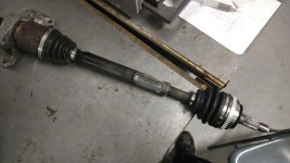
did you need custom shafts? or did you hack something in there..
i wonder if you will snap one with a good set of rubber
-steveo
Yup quick install I use scrap steal to mount the motor. its solid... Spins smooth no need for rubber mounting.
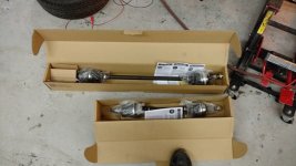
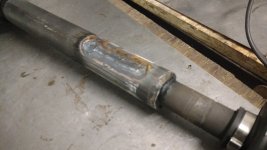
I found the Honda Shaft OD was about .040 smaller then the Nissan Shaft ID and the Honda shaft was solid the Nissan was hollow so I was able to slide the Honda shaft into the Nissan shaft and weld the end.
My welding shop/fab shop friends have a suggestion on how to do it better by cutting a slot in the Nissan shaft with a cutting disc as they are super hard and no drill bit will touch them. What they suggest is cutting a slot on each side about 2 inches long and filling it with weld to distribute the torque down the shaft and not in one spot.
What I have now is welded in a circle around the shaft and it will snap.
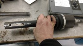
But they need to be replaced because at the start of all this I tried to disassemble the outer Honda shafts with a big 10lb sledge and they did not come apart. I am sure that's the noise you hear when I spin it up in the video.