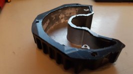
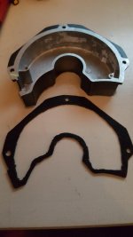
Nice to see the insides. Thanks for posting the picture.
I can't make out the numbers on the chips very well.
What's this one?

I can't make out the numbers on the chips very well.
What's this one?
E-mil said:Well, here's to the rescue, Fechter:
I can detail how to safely break it apart if you wish.. I rubber-glued it together, and it's without problems since.

E-mil said:The display is the DPC-14 aka C850 .
Here are the pics and description from my memory. Have to say I managed to break a corner of the front glass, but luckily it doesn't affect anything.
espresso said:This is presumably the modification that Luna does when they supply the BBSHD with the Ludicrous controller?
fechter said:espresso said:This is presumably the modification that Luna does when they supply the BBSHD with the Ludicrous controller?
Yes.
You don't and several resellers were dishonest about when they transitioned. Many BBSHD did not have 3077, and that was not a problem until the motors were pushed beyond 30A. You could always buy a late version controller for around $100 and keep the original for an emergency spare. I always keep a backup. I hate downtime.racingame said:Hello, how do I know if my BBSHD controller has the 3077 MOSFETS? Also, in another article regarding replacing MOSFETS for old BBS02 (https://electricbike-blog.com/bbs02-controller-mods/) it was suggested to replace with these other types:
https://www.digikey.com/products/en?x=12&y=14&lang=en&site=us&keywords=IPP034NE7N3 (mid quality)
https://www.digikey.com/products/en?vendor=0&keywords=CSD19536KCS (high quality)
Expecially the latter, I think it should be better than the 3077, right? I would like to get the least possible heat from my controller, also possibly building a totally new housing for better dissipation. I don't know if anyone else already thought about that as well.
espresso said:If I am going to be replacing mosfets with better quality and higher voltage ratings, would this be a suitable candidate for this kind of modification?
https://em3ev.com/shop/bafang-bbs02-48v-750w-controller/
")
- Yes, exactly how it works. 30 A / 24 A = 0.8 => 50 A x 0.8 = 40 AFor a 50A mod replace the 2x 5 mOhms on the rear side of the PCB with 2x 3 mOhms (Width: 3.18 mm Length: 6.35 mm, Height: 0.35 mm). Power can be lowered in programming software, for example 24A = 40A
- Never thought about that! Of course it must the controller that controls that. If voltage is too high but still turns on the system (fx at 62 V), the controller just sends error code to the display.Original display goes only up to 61.4V using 15S
DPC14 is made by APT display, what about DPC18 made by Bafang? Is this really a problem of the display or the controller itself?
- I'm not sure what you mean / no idea.Using a Cycle Analyst with shunt or shorting the orange and brown wire of the display wire (turns on controller, but level can't be switched anymore, throttle is fine)
- Yes, they have to be changed. For the cap size fitting problem, I've displayed various examples in a previous post. I did not order 80 V caps, so maybe those would be ideal if not going over 18S. I maxed out the space, but added one cap outside as well. Hell, it works!Using more than 63V the 2 black caps have to be changed. But are maybe bigger and don't fit in the housing anymore.
Seriously a good question! I have already feared that running my BBS in -5 C temps, and bringing it back inside has drawn moisture that settles on the circuit board and what-not. It's been over a month since I checked for that, where it was dry. I ought to spray it with something to at least seal the board.Have you actually filled the controller again with silicone to protect it from water? Or is more air better for cooling?
burner77 said:Using more than 63V the 2 black caps have to be changed. But are maybe bigger and don't fit in the housing anymore.
Have you actually filled the controller again with silicone to protect it from water? Or is more air better for cooling?