
You are using an out of date browser. It may not display this or other websites correctly.
You should upgrade or use an alternative browser.
You should upgrade or use an alternative browser.
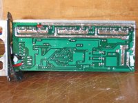
Inside a GM 48v 1000w controller
- Thread starter electraflyit
- Start date

ZapPat
10 kW
Can't help you with hooking up your CA since I don't have one, sorry.
However, thanks for the good quality pic of this controller! Any possibility of getting one of board's underside too? Pretty please?...
Anyone notice something very funny about this controller? Not quite the same as the last version I saw a pic of... :wink:
However, thanks for the good quality pic of this controller! Any possibility of getting one of board's underside too? Pretty please?...
Anyone notice something very funny about this controller? Not quite the same as the last version I saw a pic of... :wink:
It looks almost identical to the earlier ecrazyman controllers only with 15 FETs. The attachment points for the CA should be the same. Look toward the bottom of page on in this thread:
http://endless-sphere.com/forums/viewtopic.php?f=2&t=4282
I'd guess it runs two high side FETs against three low side FETs on each phase.
http://endless-sphere.com/forums/viewtopic.php?f=2&t=4282
I'd guess it runs two high side FETs against three low side FETs on each phase.
ZapPat
10 kW
That's right, 2 high side and three low side FETs! Any idea why they might want to do this? Maybe they mostly switch the high side FETs, so traded lower switching loses for higher conduction loses on the top side... but seems a bit strange to me.
electraflyit
10 W
ZapPat,
I'll get a shot for you next time I pull it apart.
fechter,
I saw that controller earlier and it seems a bit diffrent in a few places, specially where the yellow and orange CA wires go. Also their seems to be a second LED near the fets.
On my board where is the hall signal for the CA. Its a bit hard to see but on the left R61 &62 are populated and their is a transistor above them???? could it be a buffer already???
Eddie
It also sounds a bit strange to me because the high side FETs do the PWM switching!?ZapPat said:That's right, 2 high side and three low side FETs! Any idea why they might want to do this? Maybe they mostly switch the high side FETs, so traded lower switching loses for higher conduction loses on the top side... but seems a bit strange to me.
Does this controller have regen braking?
electraflyit said:ZapPat,
I'll get a shot for you next time I pull it apart.
fechter,
I saw that controller earlier and it seems a bit diffrent in a few places, specially where the yellow and orange CA wires go. Also their seems to be a second LED near the fets.
On my board where is the hall signal for the CA. Its a bit hard to see but on the left R61 &62 are populated and their is a transistor above them???? could it be a buffer already???
Eddie
Yep, I bet that's it. If the transistor is labeled Q2, then I'd put money on it. The hall signal is on R62.
The second LED by the FETs indicates battery power. The ecrazyman version has this also.
It is almost identical in most ways, but they used different wire colors in a few spots. I think you can trace them.
The7 said:It also sounds a bit strange to me because the high side FETs do the PWM switching!?ZapPat said:That's right, 2 high side and three low side FETs! Any idea why they might want to do this? Maybe they mostly switch the high side FETs, so traded lower switching loses for higher conduction loses on the top side... but seems a bit strange to me.
Does this controller have regen braking?
I think there are times in the commutation cycle when you have two high side switches working against one low side. They beefed up the low side to even out the load.
ZapPat
10 kW
This is one of the most basic ways of commutating brushless motors, and I think most regular controllers use this method:

It would indicate that only two phases are active at once. Maybe some more exotic switching schemes might have all three active at once, but this is probably not so in our typical garden variety controllers.
In a regular controller only one phase is PWM'd while the other is just pulled low during the commutation. So I guess it might be logical then to have more FETs on the low side, since they are conducting more of the time, and less on the topside would reduce transition losses.
Unless of course one uses their ebike at full throttle most of the time like many here might do!
Is this a regen capable controller I wonder?
electraflyit
10 W
I took a shit load of photos when I had it apart, none of them has a clear shot of the transistor to check if its marked Q2, bugger.
It was bought as a standard controller, no markings on the outside at all. The regen controller on the site looked different and was dearer.
Looks like I'm going to pull it apart again and have a better look this time, and get a shot from the rear (for ZapPat)
Eddie
It was bought as a standard controller, no markings on the outside at all. The regen controller on the site looked different and was dearer.
Looks like I'm going to pull it apart again and have a better look this time, and get a shot from the rear (for ZapPat)
Eddie
ZapPat
10 kW
electraflyit said:[...] and get a shot from the rear (for ZapPat)
Eddie
Sounds like I'm in for some good controller pRon! :lol:
I think ZapPat is correct about the timing. I saw a goofy chart somewhere that was not typical.
Anyway, the PWM usually happens on the high side, and extra FETs are located on the low side. Since the low side does not switch very fast, it would be easier to drive a bunch of them in parallel. It would reduce conduction losses.
Another consideration might be if the low side FET body diodes are doing the freewheel diode function and therefore generate more heat during PWM. I'm not really sure how the collapsing field pulses are being circulated during commutation. I haven't seen many controllers with synchronous rectification.
biketrials
1 mW
- Joined
- Jul 30, 2008
- Messages
- 14
What i said was that GM *motor* hall signal does not need buffering to run CA speed sensor. I dunno about your motor.
As for the controller, my crazyman 48V 1000W has a buffering circuit on the board, and the output of that is one of those single wires (see crazyman thread) and i think the PCB pad was labelled BS.
Your controller does not have these wires, and doesn't look like the buffer circuit is there on the board. But it's been a while since i've looked at boards.
Anyway just hook up your speed sensor wire to one of the 3 hall inputs and try your luck if it works.
Show us the back of your board so we can see what the extra 3 FETs are for... From the PCB component numbering, it looks like the extra 3 are all on the right there, which disagrees with the 3 on the low side theory.....
ZapPat
10 kW
biketrials said:Show us the back of your board so we can see what the extra 3 FETs are for... From the PCB component numbering, it looks like the extra 3 are all on the right there, which disagrees with the 3 on the low side theory.....
I think they are just a bit slack with their component numbering, since we can clearly see that the ground trace goes to the source of what would logicaly be the three low side FETs. On top of this, the three phase symetry would not be right anymore if we look at were the phase output wires are (right between the 2 hi-side FETs and the 3 low-side FETs of each phase).
Hey Eddie, could we also get a photo with a bit more front angle so that we can see all the FET numbers too if possible? Thanks!
electraflyit
10 W
Similar threads
- Replies
- 18
- Views
- 763
- Replies
- 12
- Views
- 412