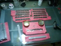
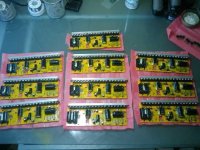
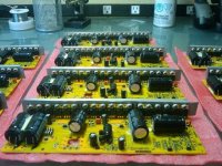
Instant Start 18 fet Infineon Boards are here...

Anyways, I'll take a quick crack.

Phase wires - All the way to the motor or short

For simplicity of end user installation, all the way to the motor. It should only be a few more feet which should mean not so much increased cost. However, I haven't thought through the "motor connector" issue, but, it seems like motor wires are generally kept short and setting up an extra wire with two extra connectors in between the controller and motor introduces resistances losses and just more difficult installation. Although, those european style terminal blocks are awesome I've found! I think I've found connector nirvana with those!

Power wires - 45A anderson, 75A anderson, bare coper

45A would be more readily available, they're more common and they're cheaper. If someone plans to be launching huge currents and feels uncomfortable past 45A, I think they can make the upgrade if necessary. The 75A ones are just... huge and add unnecessary expense to those who wouldn't use them and would add to the cost.

Phase and power wires - 10 AWG or 8AWG

I personally think 60 amps through 10 AWG wire is fine on a bike, and 10 gauge wire fits into more connectors. 8 awg isn't exactly a more readily justifiable improvement in terms of performance and cost.

Brake connector - Yes or no

Many would find it useless, but I find the idea appealing, especially if cruise control is used in conjunction. It's also nice for those "shorted throttle" situations and those with sticky throttles.

Cruise Control - Yes or no

If it doesn't add a per unit expense, then it should be included. As far as practicality goes, I don't think it's needed but I can imagine how it might be appealing to a few.

3 speed - Yes or no

Uhhhh? What? Are you suggesting you'd program three user definable "speed limits" with the microcontroller that would be switchable during biking? I'm sure that would be nice to a few, but I don't think I'd find particular use for it. Welll...... maybe, just maybe, if I didn't have a speedometer of some type, it might be nice to limit the speed to a known value so that way I don't "accidentally" go too fast.
 
Love the vids, and the little USB/micro widget. :)

120A huh... hmm... I may to beef up my 5304 wires a bit more, like 10-gauge. :roll: I'll start with a 24s5p a123 setup, which can easily supply 120A. Should be fun. :mrgreen:

-- Gary
 
hi
with that short a video a soundtrack could not easly be chosen and size was my first priority.
on wires and other things:-

phase wires: 10 swg for most aplications thicker on request must have a good reason for it like doc and his drag racing or maybe an 5x commuter over hills.
connectors anderson 45A crimp widen the crimp to get all the wires in prior to crimping is my method of getting all the strands of a power cable in.
Length should be to order as there are several places to mount a controller and as methods said in a PM to me and I agree you want a straght run from controller to motor no coiling up the wires.

Battery wires: 10 swg also 8 swg woud be better for the 100A + controllers (8 swg will require a bit of work on the board to make them fit this will add time and work)
connectors 75A would be a better choice IMHO, if 8 swg used then no question 75A
length the same should be to order, for the same reasons. Plus sell 8 swg by the foot for the battery wires.

hall wires: size is not a problem.
length is not so critical but considering the cost of the thin wire used (though I'm not sure of the way methods has chosen) the same length as the phase wires.

Thinking of construction fitting the wires last may not be pratical and or fitting the connectors methods may well find it easier to make up a load of cables all at the same time first fitting the connector then feeding into the controller if so he would want to waist as little cable as possible so a standard length would be best, maybe he has several standard lengths that he cuts to length for you but you have to pay for the full length ( if you want say he can give you what he cut off) this would give us what we want and make things easer for methods.

programing: an on board USB connection does not sound like such a good idea, a 4 way connection to the programming port on the board and a USB to TTL converter cable as was used on the earlyer infineons sounds better, I'm not sure the USB converter could take being in the controller case.

finally all the little bits and things that the infineon can do:
methods is absolutly right every extra takes time I have to alter the 12 fet boards that come over from keywin to Team Hybrid before he can use them this all takes time and will up the cost of the controller.

As the Infineon controllers are a family of controllers most if not all of the features I have found while testing the 12 fet controllers will work on the 18 fet I found all the familiar pad names on the pics, I hope to find more features as a better chip is used and a new program. all the things I have found out I will freely share and give opinions on how usefull I found them and think they would be for diffrent situations.

Geoff
 
GGoodrum said:
Love the vids, and the little USB/micro widget. :)
120A huh... hmm... I may to beef up my 5304 wires a bit more, like 10-gauge. :roll: I'll start with a 24s5p a123 setup, which can easily supply 120A. Should be fun. :mrgreen:
-- Gary

I was going to spend today beefing up the 9C for another test but... You know what? This controller is not going to blow, .... My 9C is :?
I think I will just ship it out to you. I dont really know what the current limit is :roll: but as soon as the software comes in you will be able to adjust it.
Maybe I can load it down with my Cyclone motor and get a clear Amp reading.

I think I will spend today working on the production line.
I would like to fill out two more controllers and get some more bugs worked out.

I am stuck going to my Mothers this weekend to work on wedding stuff.
Arg!

-methods


P.S. Thanks for the feedback guys.
 
Can someone please confirm something for me?

Here is a picture of the throttle connection from Ebikes.ca
Rectangular-3-Pin-Connector.gif


The controller has the pigtail on the left, the Electrical Sockets

It just so happens that the brake is the connector on the right.
Could someone please confirm the pinouts and describe it in terms of that picture?

Here is the original info on the xlyte thread but the ordering is not clear
http://endless-sphere.com/forums/viewtopic.php?f=16&t=8977&start=45#p137991

At some point in time I think I adopted a different pinout for my Kelley. Now I need confirmation.

Whenever you have a component with multiple connectors that can mate it is CRITICAL that if the end user plugs those together it does not cause problems.
For instance, when using the 6 pin for both the CA and the Hall sensors, if the layout was not correct it could be possible for a user to feed the Main Battery Voltage right back into the 5V buss :shock: I accounted for this and there is no possibility for problems.

I would like to confirm that the same is true for the throttle.
If the throttle is plugged into the brake then ideally:

+5V would go to +5V, Throttle ground would go to brake control and brake ground would go to throttle control.

-methods
 
hi
an older throttle connector was a 4 way version used to allow for a power level indicator throttle to be used, somtime called a 3 or 4 LED throttle justin droped it as in the rain the connectors could short and cause a runaway motor WOT I had this happen to me it was not very nice to watch your bike shoot off into the rain while you had it left on the stand. the reason is that the 4 way connector has ground, +5v, throttle sensor signal and full power the fault happened when there was a short from the throttle signal to the full battery voltage, I like many others still use the 4 way connector to remove the chance of missconnections but only use 3 of the 4 connections, I have just started to use that last connection with a throttle that keywin sells, a full grip throttle with a green button momentary make switch on it, this last wire can be connected to the X1 pad then you have a throttle that works in cycle mode, which is what I have been asked for by Team Hybrid, and by choosing the speed setting carfully I was able to get the controller to work with both a standard or green button throttle.

main thing is use 4 way connector with ony 3 connections if you think this will work I have the pinout.

Rectangular-4-Pin-Connector.gif


just don't connect the V-batt wire.

Geoff
 
Thanks Geoff
I purposely steered away from the 4 pin for the reasons you quoted as well as the fact that I dont think an LED "fuel gauge" is useful in any way. I can see your point about using a throttle with a button but I dont want someone with an LED throttle plugging in and thinking it should work. I will stick to the 3 pin for now.

I was actually after the pinout for the eBrake.

-methods
 
methods said:
Thanks Geoff
I purposely steered away from the 4 pin for the reasons you quoted as well as the fact that I dont think an LED "fuel gauge" is useful in any way. I can see your point about using a throttle with a button but I dont want someone with an LED throttle plugging in and thinking it should work. I will stick to the 3 pin for now.

I was actually after the pinout for the eBrake.

-methods
hi
a LED throttle will work the LEDs will just not light up the throttle part and the LED part are seperate except for a common ground.
useing the LED system is A not very acurate and B will blow up when used at the voltages this controller is best for.
as I said just have 3 wires coming out of the controller and you would have no problem.

The xtlyte brakes are hall and i am not sure if they are compatable cannot see why not, I have a pair here but I never tried to get them to work with the Infineons it would require a ground wire,+5v and a signal wire, they are made from plastic and have short reach levers(2 finger) keywin sells a good set of metal levers with microswitches in them how they will stand up to the test of time I do not yet know on the positive they are 2 wire signal and ground and full length (4 finger) levers, if you go for these or any other of the microswitch type lever then only 2 wires are used.

Geoff
 
Making Progress...

Fets_003.jpg


Going to have to talk to Keywin about the QC on these heat sinks.
I have done 20 of them now so I am a pro but I could see people having a real hard time if they have never built a board before.
Each one of them will technically achieve isolation but some of the phases are real close.

So far I have only screwed up one and that was due to cross-threading a screw.

-methods
 
Looks good Methy! Very professional!

-Luke
 
(Above) NICE!

Caps are glued down
Heat-sinks are mounted to the boards
Isolation tests are done

Fets_On_001.jpg
Fets_On_002.jpg


-methods
 
MMmmmm I see power ! :twisted:

Excellent job Methods!

Doc
 
Im gonna drive by your house and steal them all, its on my way home...

those are BEAUTIFUL btw
 
Hi all,
First up, thank you Knuckles, geoff57, Keywin, methods and others for your combined, cross-cultural innovation in motor controllers! I have been reading with great interest as the features and capabilities of your controllers keep expanding. :D
I've also been inspired to build a new ebike by developments in the RC-motor threads. I started with an Chinese ESC, but for want of quieter, high voltage and full-featured control I'm am now following the lead back to ebike controllers in combo with Hall sensored RC motors.

:?: My question: is anyone planning to produce these instant-start controllers in the 12, 9 and/or 6 FET catagories?

I'm looking to build a 45-50A (and also a 30A) instant-start version of methods' 50A moded, 6FET Infineon - small, cheap and effective.
 
hi
the word on the grape vine is that there will be 12 fet instant start controllers, maybe with the same chip as the new 18 fet has, I will keep you posted unless methods hears somthing first.

Geoff
 
I'm searching for great replacement capacitors to upgrade to 160V, but the form factor is not easy to organise!!

100V operation is preferable with 160V caps

The stock capacitors are 100V 1000uf and have 18mm x 40mm. allowing a safe max voltage of around 85vdc.. but the HV spikes generated by the inductance and capacitance of the circuit is higher than 100V whne operating 100V..

The max space between the board and the case lower top is 1.00"... so it's around 25mm.. but some caps are monten on the top od some smt components, reducing the height for diameter availlable of around 22mm dia max capacitors

I've searched at digikey and the max uF value for 160V to respect the same original size of the 100V 1000uF is 470uF

I'm wondering if instead of buying small caps it would be better to buy like 22mm dia x 45mm long that have 1500uF and to put less of them... also the low ESR capacitor come only i very unapropriated size!

Any suggestion for 160V caps that keep all the original capacity total value and that can fit in that case?

I also see that the shunt have been relocated allowing larger capacitor size close to the input current..

Doc
 
Methods, to operate at 100.8V, did you needed to replace some regulator resistors?

Have you did any calculation about the current, save operating voltage margin about the regulator?

Doc
 
This regulator works by putting 3 power resistors in parallel
This makes for much higher power handling than the old design
I consider the below conservative numbers. Even at the 70V - 105V setting I have run 44V and it worked fine.

1.8 || 1.8 || 1.8
input 70v~ 105v

1.5 || 1.5 || 1.5
input 60v~ 86v

1.8 || 1.8 || 0.68
input 50v~64v

1.5 || 1.5 || 0.68
input 30v~54v

I sent you 3 of each.
This regulator has GOT TO GO!

I am considering sending a free controller to anyone who has time to reverse-engineer this newest regulator design and come up with a new "Any-Voltage-Mod" (coined by Knuckles).

Unfortunately I am in the middle of a wedding crisis (7 weeks till the wedding, wedding planner quit, we lost the location, pissed off the caterer, etc.)

I have secured a translator and I am working with Keywin to solve many of these silly problems.
Soon we will have a 10KW controller that is unbeatable.

-methods

P.S. 100V caps are fine for 100V assuming they are high quality low ESR. Like fechter said - it is about the quality of the capacitors. Better to have 100V low ESR caps than 160V "so-so" caps. I would rather have more capacitance at 100V than less at 160V as well. for people running more than 24S - they will need 160V caps for sure.
 
methods said:
II think this is going to boil down to whether we want to build a controller for the masses or a controller for the insane.
The price of the caps wont be that much but the labor keeps increasing.

how many other people out there are actually running 24S lipo or equ?
Probably only 5 or 6 of us
I bet most people are running more like 70 - 80V tops.
If this is the case, we are set as is.

-methods

I'm running 24S A123 on my X5304. I want the best 0-30 time I can get.

My vote is make one for the the insane. If your going to do all this work. Might as well take it to the extreme.
 
Right, but 24S A123 is only 80V nominal.
I think the original discussion was revolving around how Doc is pushing for 160V caps
I was arguing that 100V caps are plenty for most people, you included.
I am even running 24S Lipo on the 100V caps without issue (yet) and these are the caps from China.

You will get better performance with more capacitance at 100V than by bumping up to 160V and losing capacitance.

I agree with you though, no point making anything less than a monster.
I really dont think we need to worry though. I dont think anyone here (on a bike) can draw more current than this controller can handle.
If we get into the motorcycles... Then maybe we will hit some limitations - but my guess is that they will be practical limitations, - like wire gauge.

-methods
 
methods said:
Right, but 24S A123 is only 80V nominal.
I think the original discussion was revolving around how Doc is pushing for 160V caps
I was arguing that 100V caps are plenty for most people, you included.
I am even running 24S Lipo on the 100V caps without issue (yet) and these are the caps from China.

You will get better performance with more capacitance at 100V than by bumping up to 160V and losing capacitance.

I agree with you though, no point making anything less than a monster.
I really dont think we need to worry though. I dont think anyone here (on a bike) can draw more current than this controller can handle.
If we get into the motorcycles... Then maybe we will hit some limitations - but my guess is that they will be practical limitations, - like wire gauge.

-methods

Het Methods, I just bought 50$ of high high quality Panasonic HC capacitors (-40°C ~ 105°C).. still 1000uF and 160V and low ESR with 22mm x 40mm size.. it's 4mm larger diameter but they will fit!

so i'll have more capacity.. i'll replace the actual 470uF for 1000uF and will still have 1000uF for the 1000uF.. so it will be 1060uF more for a total of 5000uF at 160V instead of 3940uF at 100V... operating capacityr without safe voltage margin will make them to age faster and their ESR will increase as they age.. that is something to know :wink: .. it's similar to battery aging.

TSHC%20SERIES%2040,22D.jpg


Doc
 
How much more expensive are the 160V caps than the 100V caps?
If they are similar price and they fit as well as you say they do then I will consider them
I can tell you right now though.... 4mm is a lot!
Currently it is a tight fit with all that 10 AWG wire in there.

I suspect that you will get interference with the 10 AWG and it will cause you to have to route around them instead of over them
(which I guess is ok)

-methods
 
Here is what solution i found :
 

Attachments

  • larger 160V caps layout.JPG
    larger 160V caps layout.JPG
    82.5 KB · Views: 3,705
Doctorbass said:
Here is what solution i found :

I used 3 1000uf 200v capasitors in my 133v controller!!

my diy controller still running strong :D

-steveo
 
Back
Top