
Well I found one of the three fets is shorted and seems it is nfg. Good thing ebikes.ca is just across the ferry shouldnt be to long for the parts to get here. As for the three that were conducting to the heat sync one of the little plastic insulators was distorted a little and the screw was touching the inside of the fet a touch. Should have it fixed up real soon and now I know which way to connect the phase/hall wires!
You are using an out of date browser. It may not display this or other websites correctly.
You should upgrade or use an alternative browser.
You should upgrade or use an alternative browser.
Instant Start 18 fet Infineon Boards are here...
- Thread starter methods
- Start date
As for why it happened I probably caused it my self. I had two major problems #1 I put the wire on the traces first to build them up and that warped my bord so I had to try to un warp it as I went. I also put the heat sink on upside down and had to flip it making everything a realy bugger to get right. I did clean all the flux off I could from the bord but when dealing with 100v and 150+ amps It is easy to leave something that will mess it all up. I just recently got stupid buisy and I may have over looked something as well. At least being this buisy meens money isn't quite as tight ") I might have to get one or more methods bords for other cool projects in the future and posibly a backup!
I might have to get one or more methods bords for other cool projects in the future and posibly a backup!
I might have to get one or more methods bords for other cool projects in the future and posibly a backup!BenMoore
100 mW
Hi all.
Here's a summary of this thread I made as preparation for my 6 FET 116 controller project that its been suggested I post. Its mostly just cut and pasted but will save people wading through the 51 pages of this meandering tale to find the right tech stuff :wink: I've updated it to include recent info also.
Cheers, Ben.
Summary notes re building 116 chip 18 FET controllers
Re preventive mods/proceedures:
Methods:
Check for PCB traces near the case and coat/trim if nec.
I cut back the +5V trace at the corner on the top and bottom
I also cut back the VCC trace next to the big caps on the top left corner
Make sure you put some glue over the cut traces so as not to leave exposed copper
Discharge the big caps before removing/returning a board to its case [short them thru a resistor. Or, disconnect the battery with the CA still connected then switch on the "ignition" switch (from Vcc to Vcc-L) the CA should come on discharging the caps.]
Testing:
Methods:
When you are done take these measurements at a minimum:
Resistance: turn on the controller (with no battery attached) to drain the caps before test. If there is voltage in the system (even a little) it can give you screwy measurements.
+V to GND
(Should *not* read low resistance, but will read some arbitrary value in the Kohms - maybe 10K ohm)
GND to +V (habit, stray voltages can fool you, always reverse the leads)
(Should not read low resistance, but will read some arbitrary value in the Kohms)
Heatsink to +V
(Must be totally isolated - completely as in no change what so ever on the meter - not even a blip - OL)
Heatsink to GND
(Must be totally isolated - completely as in no change what so ever on the meter)
Building up traces:
Can use solder wick or bus wire - If you can get the iron up over 700F and use high-flux solder it is easy.
see pics p 21 for the various locations to build up
Re controller features:
Methods:
We considered wiring in all the functions like Cruise Control, Regen, Multi-speed, LED Indicate, etc. but I think that simplicity is better, cleaner, and more reliable. We can add those features upon request. I was considering bringing all those features out on one large connector and leaving it to the user to chose what functions to use. For now we are going to keep it simple for the serious ebike folks.
I really like Justin's idea of keeping it simple.
I also like the idea of bringing out one master connector that has all the bells and whistles in it that most people wont use
-
Your idea of adding an optional sensor is actually fairly easy.
In that case, I would add a micro controller to the mix with an opto-isolator
For instance, the uC could limit the throttle setting to 50% (like the CA does) if the input voltage (say and RTD) crosses a certain threshold.
Something like this is an investment up front but nearly free on the back end.
I work with a specific uC (the MSP430) that comes on a board the size of your thumbnail with everything ready to go - A/D's, D/A's, Capture Compare, Timers, Counters, Digital I/O, a 16Mhz clock, Ultra Low (sub 1uA) power consumption, ...
geoff57:
I have just started [to use a 4p] connection with a throttle that keywin sells, a full grip throttle with a green button momentary make switch on it, this last wire can be connected to the X1 pad then you have a throttle that works in cycle mode, which is what I have been asked for by Team Hybrid, and by choosing the speed setting carfully I was able to get the controller to work with both a standard or green button throttle.
-
The xtlyte brakes are hall and i am not sure if they are compatable cannot see why not, I have a pair here but I never tried to get them to work with the Infineons it would require a ground wire,+5v and a signal wire, they are made from plastic and have short reach levers(2 finger)
Connectors:
Doctorbass:
What i do for real 10 gauge with 30A anderson is that i only solder them.. it is so thight than just soldering them give a very low resistance lost...
You can enlarge a bit the hole in the connector to allow the full size of the 30A anderson connector.. .I use a long nose plyer nd enlarge it and it fit well..time saving!
methods:
If you have ever tried to make 45A anderson connections to 10AWG wire without the special tool you will know what hell it can be...
Sure it is easy enough to crimp them, but getting them to fit into the housing is nearly impossible.
Some people just shove them in there with force, but that fubar's the connection. The tabs must move freely in the housing.
Re heat sinking:
Stevo:
What i can not stress enough is making sure you have 100% thermal contact ..
I've had over a dozen controller blow due to poorly machined sinks that where warpped .. CHECK THAT BUS BAR .. put it on a flat surface .. see if any of the ends rock .. put a flat edege to the bus bar and check if its flush by eye ..
properly thermal paste everything .. Done overkill on the paste .... just put enough!! can't wait to see your results!!
[Don't need paste with grey pad b/t FETs and heat spreader. Can also use Kapton tape here. Kenny doesn't combine with paste but others recommend paste on none adhesive side.]
Doctorbass:
Also a great upgrade would be to use true MICA instead of that grey "rubber".. the heat transfer is alot better! and would make the jonction work cooler... giving higher current capability!
Shunts:
Methods:
The shunts that Keywin put in are NOT matched to the software. The software expects about half the impedance. If you want to get up near 100A cont. you must solder the shunt down to 250uOhms. If you lay two pieces of solder wick on top of the shunt and then drench the entire thing in solder you should get close.
1 mOhm: allows stay in the high resolution mode with the CA (2.5W loss at 50A)
[However] the CA actually has a very good input resolution so you may not even take a hit on your Ah readings [by using <1 mOhm].
Only need to change/mod shunt if max current will exceed the shunts power rating or if power loss is considered too wasteful (eg >2.5W).
Calibration:
methods: I am working on a new shunt programing method that can be done externally to the controller. During assembly a "best shot" is taken to get the shunt resistance near 250uOhms. I then complete assembly.
A 10A current is run from one of the 3 phase wires, through the internal diodes of the 4110's, through the shunt, and back through the main system ground.
With the CA already installed all you have to do is monitor that current on the CA and on the ammeter.
Apply the percent difference formula, repeat twice, and you are done.
No more sketchy alligator clips etc.
I got this idea from Justin in another thread many moons ago.
The 10A comes from a 5V 20A supply with some inline resistance.
More details p 29.
[Me: Couldn't I just send a sense wire out some distance (Approx 10" of 10ga = 1 mohm) up the GND batt wire to pick up the V drop? No extra power loss or heat required to measure current and stay in the high resolution mode with the CA. One issue is the high temp dependence of resistance in copper - not too bad to have the current limit drop with temp but instability of shunt resistance will effect accuracy of Ah calculations. Shunt calibration would also be required. Need to know temp change of batt ground wire durring operation to evaluate. ]
Re. caps:
Glue down with quick grip/ silicone (non vinegar type)
methods:
100V caps are fine for 100V assuming they are high quality low ESR. Like fechter said - it is about the quality of the capacitors. Better to have 100V low ESR caps than 160V "so-so" caps. I would rather have more capacitance at 100V than less at 160V as well. for people running more than 24S - they will need 160V caps for sure.
Doctorbass:
The trick would be to put many low uf value in parallel over the rails.. that would be more stable for capacitance and inductance for the mosfet.
dnmun:
it may be worthwhile to reconsider the placement of the caps also and the type of conductor from the battery perhaps a ribbon rather than a round conductor, and mount the caps very close to the main S/D <Sink/Drain?> busses to reduce the total inductance. keywin added some at each end, but it may behoove you to consider having the case open to test out the idea of using large caps soldered directly onto the S/D busses from underneath, perhaps having them sticking out the bottom, normal to the pcb. the legs should be as short as possible, not sure if the voltage rating will matter that much then.
liveforphysics:
We seem to be going about it the wrong way. We aren't concerned at all with storing energy in these caps, that's why we have batteries. We have the caps to resist the change in voltage each time a FET bank switches on or off. The peak capacitance we need to be store to do this is under 50uF (from my crude estimation).
All the effects our performance is the final ESR of the system of caps we use. In other words, any cap solution that provides a lower combined ESR, regardless of the capacity values is going to result in higher performance.
-
Rubycon makes some caps that look pretty good, but you would need 3 in series... which would be lame to setup.
35v 470uF 0.014Ohms ESR 10mm x 20mm
So, it would be 42mOhms for a 105v cap with 156uF, and it would fit in a very small space. I think using a group (3s8p) of these caps you could get a board down to maybe 5mOhms.
dnmun has 30 cent 100V 1000uF caps for sale from eBay
4110 FETs:
greasypants:
I known Lowell said the 4110's should be ok up to 112 volts but I have never tried it.
Re. voltage mods for Voltage regulator for control circuit::
methods:
This regulator works by putting 3 power resistors in parallel
This makes for much higher power handling than the old design
I consider the below conservative numbers. Even at the 70V - 105V setting I have run 44V and it worked fine.
1.8 || 1.8 || 1.8
input 70v~ 105v
1.5 || 1.5 || 1.5
input 60v~ 86v
1.8 || 1.8 || 0.68
input 50v~64v
1.5 || 1.5 || 0.68
input 30v~54v
[Can also use a switch to change resistance for 50V and 100V modes. See methods' 100V 100A controller thread]
If going over 75V, should replace voltage regulator SMD resistors with higher power, leaded one/s ( total R = 3K , Power = 3W). see p 17 and p 21 for pics
dnmun:
why not do what knuckles did originally with the infineon transistor modification. first he latched the 12V rail with the 15V zener and then latched the input of the LM317T at 51V with the 36V zener, maybe you could go extreme and use an 18V zener to latch the 12V bus and add a 40V zener on top to peg the VR input to 58V-Vbe. that would work with the 107V Vcc, dropping the 50V with a 1k6R and 1k5R 2W in parallel. about 3.2W total. plus it would run all the way down to LVC on the battery pack then too. my education from knuckles. - methods says: too much work for production model.
SAM-pilot: For voltages over 86V you need to lower R12. Otherwise you will have a overvoltage on the voltage measurement input of the uC. I have lowered R12 to 960R, which is good for input voltages till 107V.
Doctorbass: .. just replacing the 3 serie resistor for a 3.0K 3Watts and replaced the 3 parallel 3W flameproof resistors for 3 x 2.4K,
I have absolutly no problem using up to 105V input and up tp 172A using 18 PURE IR 4110 mosfet on cooper bar heat sink.
Wiring:
methods:
pics on p 21, p 26 is v good (but the throttle position wrong throttle output is to the SP pad, TB is to do with 'securety' which is all anyone knows)
Also: methods: Please check out Knuckles threads in the Technical Section, everything is clearly laid out (Most everything still applies. The regulator is different, the programming hole is a little different, some locations are different. All of the "normal stuff" is still the same though.
"Infineon Controller Technical"
Hall – 6P
RED - +5V
YEL - GND
GRN - A
BRN- B
GRY - C
BLK - N/C
Throttle – 3S
RED - SP
YEL - GND
BLK - +5V
Brake – 3P
RED BRK
YEL GND
BLK +5V
CA – 6S short
BLK VBAT
GRY GND
BRN SHUNT-
GRN SHUNT+
YEL SPEED
RED THR_INH
(bikeraider has pics of CA wiring p46)
If you analyze the way I set up those pins it will be come apparent that I did 2 things:
1) Maintained compatibilty with the Crystalyte Throttle and Brake as well as the CA
2) Set it up so that plugging the connectors together in an incorrect manner will not cause damage.
Q: On the CA connector, do you wire the Ebrake to the EB+ or EB- ?
A: There are 2 ways to do it:
1. Brakes Only: EB-
(EB+ would be for a 12V input)
2. Variable Throttle Control by CA
(Follow instructions for CA, attach to throttle line)
Q: On the CA connector, where to wire the Hall to the amplified hall circuitry on the board?
A: Attach it to any of the three hall signals, A, B, or C. [I think methods drills a hole and taps a hall on the bottom of the board. BTW, don't worry abut "the amplified hall circuitry on the board" it doesn't seem to work].
Q: Is the ON/OFF switch use for enable the controller circuitry? If so, should I connect the VB2+ & Vcc-L?
A: Connect the switch between V+ (anywhere) and VCC-L
I suggest drilling a hole on the left side cover between the top of the caps and the fets.
This will lock in the switch and allow you to tighten the nut while still allowing easy assembly and access.
Remember to power the CA from VCC-L so that when you turn the switch off the CA turns off.
Q: 5v E-brake for c/a?
A: The ebrake is EBS-
Just apply your active low to this pin.
Dont forget to solder the diodes I gave you into D32.
You can run the CA there or you can run the CA to the Throttle line via a diode and a resistor per the CA Instructions.
Q: LED: Led Ground?
A: To me it just looks like Doc hooked an LED into the VCC-L circuit
Button is on, LED is lit
Button is off, LED has no power.
geoff57: I think Doc found somthing about what LED did I'm not sure.
p1 and p2 are for leds they will show what "gear" you are in p1 for speed 1 p2 for speed 3, now P3 can have 1 of 2 uses depending on how you set it in the software, it can be set to indecate that cruise controll is active or it can be set to a diffrent function as normal chineese to english translation was not up to the explnation so I will have to workit out myself but whatever it is it is anothe led indicator.
methods: I would not bother with all the trouble of a Status LED. The CA turns on and off with the board and that is a much better indicator of status in my opinion. The diode just makes for a lot more work, more current draw on the regulator, and one more thing that can go wrong. You have to drill a hole for it, glue it in, calculate a current limiting resistor, bah!
USB programming cable:
Ships with a mating header connector.
Solder that into the row of holes right above the date stamp.
Orientate it to the left. You can confirm you have it right by seeing that the red/orange go to +5 and the black goes to ground.
Software/ programming:
See page 12 for translations
See page 18 for S/W installation instructions
Connecting controller to computer see p 19
A driver is required for the USB to PC link.
Knuckles has downloads on p 25
.OCX files are no p 41 if needed (ie computer reports them missing)
See method's settings and procedure p 22
methods: The purpose of my mod is to allow you to solder in the header and program the controller after the case is on.
An alternate to my mod would be to solder in the connector and then add a second connector that could be broken/reconnected outside the case to transfer.
No matter what power must be toggled to transfer data.
[When flashing has occured, a program bar goes across screen and the message box tell you that you were successful].
You need a switch on the negative pole of the USB cable to activate de transfer data. [ZapPat doesnt use/need a switch. See his post p51]
geoff57: by setting the block time to a large value you can go over the [software, "57A"] amp limmit for a short time.
Other software parameters:
"Bar Protect" option: ZapPat: I don't know if this was mentioned before, but the "Bar Protect" option in the parameter designer software is actually a throttle fault protection feature. If your throttle cuts off when close to it's full position, then deactivate this option to get it functioning normaly. Gotta love these funny translations!
"Tolerance(V)": SAM -pilot:
I am quite sure that "Tolerance(V)" is a delta voltage. After a low voltage cut off the input voltage needs to rise the programmed "Tolerance(V)" over the low voltage level to turn the controller on again.
One time I have programmed the "Tolerance(V)" to 1V and as my battery voltage gose down to the low voltage level at high current, the motor goes on off on ... quite fast. [hysterisis for the LVC]
Also see Infineon Programming Help thread (applies to 116 chip controller also)
http://endless-sphere.com/forums/viewtopic.php?f=2&t=13139
Pics:
Doctorbass's inside view - p13
Diagnostic LEDs:
Doctorbass knows where to put - can kind of see in his pic p 13 (and geof57 also I think)
External current adjuster:
Alternative to using a 2- 3 speed switch.
Doctorbass: installed a 10K pot + a 4.7K in series to replace the R44 10K resistor that set the current sensing amplification that the Uc reads. Update: "I removed the external pot and resistor cause the that induced alot of noise and alarmous current spikes at low RPM."
Regen:
Enable in s/w
For regen to activate you must jumper BK to GND - see pic p 26. Grounding BK switches on the regen circuit so when the brake
is pulled regen is applied at the same time( knuckles has a regne brake button as well, just a button wired to the Ebrake line, as a brake an uses that to brake a lot pure regen braking ).
V max mod:
Stock max on the 18 FET is 75V, set by R12 at 1200Ohms.
geoff57: check first [as "75V" may be lower than actual max allowed]
SAM - pilot: For regen at a higher voltage then 75 you need to make the LVC mod on R12. I have lowered R12 from 1.2K to 960R. This means the real voltage is the programmed voltage +25%. So 75V max regen voltage is now 94V.
note: Lowering the R12 value will increase the (programmed) regen voltage limit and also increase the (programmed) LVC.
Knuckles:
In theory, regen braking voltages should be limited according to the battery in use on the EV.
24V battery … Max charge voltage = 30V.
36V battery … Max charge voltage = 45V.
48V battery … Max charge voltage = 60V (default Infineon value).
60V battery … Max charge voltage = 75V.
72V battery … Max charge voltage = 90V.
(Note that regen braking is disabled by the processor over the max charge voltage.)
In reality, it is virtually impossible to overcharge batteries using regen braking in the real world.
And, of course, ONLY mechanical brakes can make your tires skid to a stop.
Also: geoff57:
"the mod was ok I think Knuckles knows more about the mod than me, I have not had DD motors for long only been working with geared so I never concentrated on regen with an X5 and a 409 I will have to now. As far nas the switch is concerned if you want to be able to switch off regen as by putting a switch in there you may want to you need a on of switch not a momentary switch, but I think you have got the whole braking system wired up wrong, what you want is to push a button and the regen is activated charging your battery and braking the bike, the way YOU wired it up just activates the regen circuitry so when the Ebrake is applyed the regen is applyed as well and since you used a momentary switch it was on then off.
Regen is used in conjuntion with the EBS or Ebrake system.The EBS or Electronic Braking System pads that are connected to ground are just a switch that stop the motor while the switch is closed most often found fitted to brake levers (EBS+ is as I said before used with a 12v brake light supply but the prisiple is the same) the strength of regen is controlled in the software and then the yser can choose when to piggyback the regen signel onto the Ebrake signel by grounding BK. from what I can gess of your setup I think you will want somthing like knuckles has he has his BKlinked to groung permantly(this is an option) then on the handlebars he has his standard Ebrake levers with a microswitch in them connected to the Ebrake EBS to GND connector, PLUS he has an extra push button momentary switch on the handlebars that is also connected to the Ebrake connector, very often he uses just the push button to stop him and saves on brake pads as well !!" more discussion p 27.
Cruise control:
Enable in s/w
geoff57: Cruise control: is activated by useing a momentary switch between CR and GND. the way it works is that you turn the throttle as far as you want to then press the cruise control switch you then let the throttle return to rest and the controller will ceep the motor going at throttle place you had it in UNTIL either the Ebrake is applied ,the throttle is turned or the cruise controll is presesd again, I think that the setting in the software on cruise controll is to do with how long you have to get the throttle to rest befor going into cruise control is ignored I am going to test this theory, at high speeds or in built up areas I would not advise cruise control.
Ebrakes:
geoff57: The Ebrakes are on the EBS pads, a switch ebrale between EBS- and GND will activate the brakes as would the output of a hall ebrake though I have Yet to test hall brakes.
Other stuff:
methods:
Keywin forgot to populate D32. This is the diode that links the -EBS (ebrake) pad trio. It is suggested that you use a 1N4007 or an M7.
12V rear brake lights:
The ebs+ pad is disabled on both 12 and 18 fet boards it requires Q6 to work and it is missing.
SAM - pilot: You need just added a NPN transistor (Q6) and then it works fine. I used a SC2240 I had in my stock. But on this one I had to adapt the pining.
SL pad:
Is for speed limit. Ground that and you get a limited speed BUT unlike the speed settings you get full torque until you reach your speed limit(this could be at only half throttle though)
Regen:
Controled by 2 factors,
1: the software settings as to how high a voltage the cut off point is , in the software this is a max of 75V not enough for 100v 18 fet controllers knuckles has worked out that a regen mod will be able to be done with no problem after I sent him some hi res pcb shots, it will require a rethink of the software lvc to make sure the lvc is still correct and the regen will have to be worked out but both of these problems are easy to solve.
2: the other factor that controlls regen is to actualy to switch it ON so that when you brake the regen circut activates, grounding BK switches on the regen circuit so when the brake
is pulled regen is applied at the same time( knuckles has a regne brake button as well, just a button wired to the Ebrake line, as a brake an uses that to brake a lot pure regen braking ).
cruise control:
is activated by useing a momentary switch between CR and GND. the way it works is that you turn the throttle as far as you want to then press the cruise control switch you then let the throttle return to rest and the controller will ceep the motor going at throttle place you had it in UNTIL either the Ebrake is applied ,the throttle is turned or the cruise controll is presesd again, I think that the setting in the software on cruise controll is to do with how long you have to get the throttle to rest befor going into cruise control is ignored I am going to test this theory, at high speeds or in built up areas I would not advise cruise control.
The Ebrakes are on the EBS pads, a switch ebrale between EBS- and GND will activate the brakes as would the output of a hall ebrake though I have Yet to test hall brakes, EBS+ is for a +12 v brake light found in say a car or a motorbike on earlyer boards this worked as the transistor Q6 is required and was surface mounted on these boards it is not the transistor is missing there is just 3 holes very few of us use EBS+ so it does not matter that much but for those that need it sam has the fix.
I think Doc found somthing about what LED did I'm not sure.
p1 and p2 are for leds they will show what "gear" you are in p1 for speed 1 p2 for speed 3, now P3 can have 1 of 2 uses depending on how you set it in the software, it can be set to indecate that cruise controll is active or it can be set to a diffrent function as normal chineese to english translation was not up to the explnation so I will have to workit out myself but whatever it is it is anothe led indicator.
Speed Limit:
the SL pad is for speed limit. Ground that and you get a limited speed BUT unlike the speed settings you get full torque until you reach your speed limit(this could be at only half throttle though)
Reverse:
the DX3 pad is the reverse switch. ground that to go in reverse. only of use on direct drive motors as regen would be, in theory it should be X3 but there is a diode missing why i don't know there holes for it .
Separate charging lines:
methods:
I will be adding new lines to the controllers for charging.
On my old bike I used to charge through the shunt so that I could measure negative AH. It is a nice feature... Just turn on the CA while charging and you can monitor Charge Voltage, Charge Current, etc.
I will be running a pair of charge wires out of all future controllers.
These will be tied to V+ and PHASE(-)
This will force the current to run backwards through the shunt and roll back AH while charging
You guys will love it.
I will size the wires to about 20A charging.
3 speed selectior:
Pads X1 and X2 grounded with a switch (only one never both at the same time so use a 3 way switch) activate speed 1 and speed 3 respectivly with neither grounded the default is used speed 2.
methods
1 GW
Look at that
Everything a nOOb (or a pro) ever wanted to know and more.
Truth be told I actually have a copy of that on my desktop that I reference when I want to know one thing or another.
Very useful collection of data
I never posted a summary because I like to torture nOobs.
It should be noted that there are a few dead ends listed in there.
- Off the top of my head the variable current limit idea that doc had was a bust
- The status LED is simply an LED hooked up to the switch so there is no "error data" in there
- There were a few other things in there that were from earlier in the thread but I cant remember them off the top of my head.
Anyhow - thanks Ben. That will help a lot of people.
-methods
methods
1 GW
Oh yea - all my new mods are being collected in the new thread.
* Better shunt setup
* Switch to go between 50V range and 100V range
* Better isolation setup
* etc
This thread is heading toward the archive.
That was a good post to put near the end.
-methods
* Better shunt setup
* Switch to go between 50V range and 100V range
* Better isolation setup
* etc
This thread is heading toward the archive.
That was a good post to put near the end.
-methods
So.... As I wait till the fets come across the small amount of ocean between me and ebikes.ca I will finish up all the rest of my work to have this thing ready. But if I get to the weekend and they are still not in my hands can this thing be run without one fet? Maybe in a 12 fet mode?
methods
1 GW
"Patience is a virtue seldom possessed by women and never possessed by men"
Friend - if it is my advice you are soliciting then hear this: I dont think you should so much as even turn that thing on again until you post detailed pictures of all your work. You may be shy - but dont worry - I have seen more naked controllers than you can shake a stick at. :wink:
It is up to you - you carry the risk of destroying the controller.
Will it run? YES - it will run on only 6 fets
Should you do it? Hell no.
I have blown up more shit than most people on this site and I can tell you this ----- 90% of the time when I blow something up it is because I let impatience get the best of me. When I start feeling like that I get one of my guns and go out back and shoot at consumer goods in perfect working order (coffee pots, speakers, air pumps...) This destruction of functional equipment always calms me and allows me to be patient.
-methods
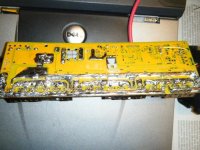
Here I will put a few picks up first of it. It is a bitch to get a clear close up and second off I have to use a low setting or else this forum wont alow them. As for the paintence thing well it is like this I use my bmx every morning to get to may shop 5 miles away then fire up my 69 road runner and laptop and log my trip 20 miles away to my job then make adjustments to all my maps according to my logs and after work I do the same to drive it back to my shop then I peddle my ass 5 miles home again. I live in an area with alot of hills and if I could not have to peddle up them anymore I would be so happy! I have a daily driver but the tranny parts are not here from france yet!
Attachments
methods
1 GW
Thanks for posting the pictures.
So lets start talking.
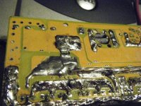
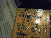
On the second to last picture the pads have been ripped out for the control and some of the phase lines.
When this happened it is highly likely that the thru-hole plating went with it. This means that you will have to re-build the traces.
For the Middle and Right fets you can just scrape all the paint off of the copper and you can probably bridge to the leg of the fet.
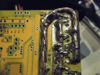
For the far right pad you are going to have to build a new pad. Best way to do this is the scrape the trace a ways back, solder in a conductor, then solder this to the leg of the fet. Cut up one of the power resistors I sent you and use the leg of that.
Let me have a look at the rest of those pictures.
-methods
So lets start talking.
On the second to last picture the pads have been ripped out for the control and some of the phase lines.
When this happened it is highly likely that the thru-hole plating went with it. This means that you will have to re-build the traces.
For the Middle and Right fets you can just scrape all the paint off of the copper and you can probably bridge to the leg of the fet.
For the far right pad you are going to have to build a new pad. Best way to do this is the scrape the trace a ways back, solder in a conductor, then solder this to the leg of the fet. Cut up one of the power resistors I sent you and use the leg of that.
Let me have a look at the rest of those pictures.
-methods
methods
1 GW
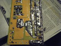
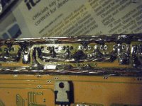
Looking closer it appears that you will be able to get away with only repairing the control pad on the left hand and middle fets.
On the far right fet it looks like Vcc is coming up from the bottom so you are going to have to patch up that pad as well.
New subject -
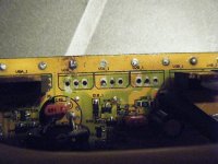
I am a little concerned that a few of the fets seem to be "riding high"
Have you checked to make sure the board has clearance at the bottom?
Remember when you solder in the 3 new fets that you REALLY SHOULD have the heat sink mounted first.
You never want to solder fets and then mount the heat sink because even if you get lucky and the holes line up it is highly likely that some fets will be under tension while others are in compression. This can tear up your traces and as the board flexes as it heats up and cools down (not to mention shock and vibration) it is likely to cause future failures.
I know that you said that you had to flip the heat sink over. This concerns me since I know that the holes are not drilled unevenly.
I am afraid that if you want to do a tidy job you may be pedaling for a while.
Where is your old controller?
Cant you kluge that up to the bike?
-methods
On the far right fet it looks like Vcc is coming up from the bottom so you are going to have to patch up that pad as well.
New subject -
I am a little concerned that a few of the fets seem to be "riding high"
Have you checked to make sure the board has clearance at the bottom?
Remember when you solder in the 3 new fets that you REALLY SHOULD have the heat sink mounted first.
You never want to solder fets and then mount the heat sink because even if you get lucky and the holes line up it is highly likely that some fets will be under tension while others are in compression. This can tear up your traces and as the board flexes as it heats up and cools down (not to mention shock and vibration) it is likely to cause future failures.
I know that you said that you had to flip the heat sink over. This concerns me since I know that the holes are not drilled unevenly.
I am afraid that if you want to do a tidy job you may be pedaling for a while.
Where is your old controller?
Cant you kluge that up to the bike?
-methods
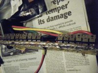
Ok so while I was waiting for video editing software and the like to take its sweet ass time on my computer I went ahead and fixed up my bord a little I re installed the 2 good 4110s and ran a jumper wire to the leg of the one I riped the trace on. When I was done I tested for continuity to the trigger on the next fet and it is good. I installed the heat sink and soldiered them back in after I then replace one of my messed up screw insulators and tighened all the fets to the heat sink then tested for sorts to the heat sink and found I had to remove one screw again and clean it carefully and it must have had a tiny peice of metal on it but now it is good then I tested all three phases to ground - and positive + and there where they should be so far till I get my last fet installed. I am trying to be paintent but I find my self thinking My Girlfriends amp is just sitting in my shop on a sub box and she doesn't want to use it or let it go so I wonder if it has a 4110 in it lol? My trace may be a little close on the bottom so I will look at it and test it maybe use somthing to sand it down a bit if needed and maybe put a small coating on the traces just incase water or some debris gets in there. So i think it is safe to flash some numbers into this thing to get ti ready I will have to go find out how to set it up for 150 peak amps for now I only have 5ah 24s lipo. As for my other controler? lol I don't waste time with fiats when I want a ferrari this is my first one lol. Methods I herd you are a ducted fan rc jet nut? Wana help me build electric boost for my 440? I plan to build a carbon fiber hood this winter and will mold places in the bottom for what I need.methods said:Looking closer it appears that you will be able to get away with only repairing the control pad on the left hand and middle fets.
On the far right fet it looks like Vcc is coming up from the bottom so you are going to have to patch up that pad as well.
New subject -
I am a little concerned that a few of the fets seem to be "riding high"
Have you checked to make sure the board has clearance at the bottom?
Remember when you solder in the 3 new fets that you REALLY SHOULD have the heat sink mounted first.
You never want to solder fets and then mount the heat sink because even if you get lucky and the holes line up it is highly likely that some fets will be under tension while others are in compression. This can tear up your traces and as the board flexes as it heats up and cools down (not to mention shock and vibration) it is likely to cause future failures.
I know that you said that you had to flip the heat sink over. This concerns me since I know that the holes are not drilled unevenly.
I am afraid that if you want to do a tidy job you may be pedaling for a while.
Where is your old controller?
Cant you kluge that up to the bike?
-methods
methods
1 GW
Did you get a chance to repair the ripped trace over on the right side too?
As far as numbers - I can email you some example setups if you PM me.
If you only have a 5Ah 24S setup you had better turn the current limit down to about 30A.
Even at 30A you will drain that pack in just a couple of miles.
If you are really using this for a 10 mile round trip you should reconfigure to 12S 2P.
Please be cautious... with a 24S 5Ah setup it is Very easy to allow one cell to drop way below LVC.
You should stop riding when you hit 80V.
Dont even think about going down to 72V LVC -> You will ruin cells if you do.
Even so - with a 35A limit there is only about 2 minutes between 80V and 72V so you are going to be pedaling anyway
I have laid off the RC for a year now. Was spending way too long building things that (given my reckless nature) would eventually just end up on fire.
Too many times I spent 20 hours laying up a bird just to hammer it into the ground at 130mph trying to do barrel rolls 6' off the ground
I used to have this tiny little uJet that had a 2200mAh 6S pack in it with a NEU 1110-2Y -> dude.... when I launched that thing it would instantly go into a high speed spin and from the time I let go of the bird till the time I got my hands back on the sticks it would be 100' away and spinning like a top. I would have to apply full opposite aileron just to stop the spinning and HOPE that it stopped right side up because by that point I would be out of field.
Eventually I made a rubber-band launcher for it but that thing was stressful.....
Very cool methods! I am going to order more batteries soon as I get it all working. It will stay in 24s mode and be 2p soon Maybe more but I just wanted to get a start to test it all out without wasting to much money on it. Pluss if you order 4 packs of 6s turnigy at a time they stay under that limit that lets them come air shipped.methods said:Did you get a chance to repair the ripped trace over on the right side too?
As far as numbers - I can email you some example setups if you PM me.
If you only have a 5Ah 24S setup you had better turn the current limit down to about 30A.
Even at 30A you will drain that pack in just a couple of miles.
If you are really using this for a 10 mile round trip you should reconfigure to 12S 2P.
Please be cautious... with a 24S 5Ah setup it is Very easy to allow one cell to drop way below LVC.
You should stop riding when you hit 80V.
Dont even think about going down to 72V LVC -> You will ruin cells if you do.
Even so - with a 35A limit there is only about 2 minutes between 80V and 72V so you are going to be pedaling anyway
I have laid off the RC for a year now. Was spending way too long building things that (given my reckless nature) would eventually just end up on fire.
Too many times I spent 20 hours laying up a bird just to hammer it into the ground at 130mph trying to do barrel rolls 6' off the ground
I used to have this tiny little uJet that had a 2200mAh 6S pack in it with a NEU 1110-2Y -> dude.... when I launched that thing it would instantly go into a high speed spin and from the time I let go of the bird till the time I got my hands back on the sticks it would be 100' away and spinning like a top. I would have to apply full opposite aileron just to stop the spinning and HOPE that it stopped right side up because by that point I would be out of field.
Eventually I made a rubber-band launcher for it but that thing was stressful.....
I know ducted fans are not ment to force air into an engine but if I used recharbile batteries to run them 4 psi from electric boost would be the same as 8 psi from my 6-71supercharger driven from the crank. Which would help keep the Intake air temp down and the internal parts would have alot less stress and it would need to burn less gas to make the same HP!
OK so I ordered 4 more packs of 6s lipo today and some balancing conectors but I was in a hurry for the conectors where do you guys get your balance conectors from and I will need the hi tention y conectors for the turnigy lipo as well where do I find them? Methods what do you do for when you connect to your power source to charge? is it parelleled and still hoocked to the controler? what about when you first hook to the controler do you use a switch?? The zaps scared my friends on the weakend! Oh and my mosfets are at my house acording to the tracking number!
methods
1 GW
Those zaps will destroy your connectors in a week.
You need to make a pre-charge circuit.
Basically you connect a resistor first to charge the caps then you connect the terminals
Buy the Y cables from Gary
Better yet, buy the LVC protection and Balancers too.

I dont use bullet connectors, I think they suck.
As far as Y and Series bullet connections you have to make them.
As far as your question about paralleling while still connected to the controller... I hope you are not asking what I think you are.
I am going to pretend that I did not hear that.
I am also going to pretend that you are not reconfiguring your pack from Series to Parallel for Charging.
I dont want to talk about it - you are going to upset my bowels.
See my opinion on the subject over and over again in the thread below:
http://endless-sphere.com/forums/viewtopic.php?f=14&t=10817&start=375#p200836
-methods
You need to make a pre-charge circuit.
Basically you connect a resistor first to charge the caps then you connect the terminals
Buy the Y cables from Gary
Better yet, buy the LVC protection and Balancers too.
I dont use bullet connectors, I think they suck.
As far as Y and Series bullet connections you have to make them.
As far as your question about paralleling while still connected to the controller... I hope you are not asking what I think you are.
I am going to pretend that I did not hear that.
I am also going to pretend that you are not reconfiguring your pack from Series to Parallel for Charging.
I dont want to talk about it - you are going to upset my bowels.
See my opinion on the subject over and over again in the thread below:
http://endless-sphere.com/forums/viewtopic.php?f=14&t=10817&start=375#p200836
-methods
GGoodrum
1 MW
Arlo1 said:OK so I ordered 4 more packs of 6s lipo today and some balancing conectors but I was in a hurry for the conectors where do you guys get your balance conectors from and I will need the hi tention y conectors for the turnigy lipo as well where do I find them? Methods what do you do for when you connect to your power source to charge? is it parelleled and still hoocked to the controler? what about when you first hook to the controler do you use a switch?? The zaps scared my friends on the weakend! Oh and my mosfets are at my house acording to the tracking number!
I will have these ready by about Monday of next week:

This combines a simple LVC board with a parallel adapter that lets you combine both the main pack leads, and the balancer plugs for up to four 6s-5000 turnigy packs in parallel. This yields up to a 6s4p configuration, paralleled at the cell level. There is one output balancer plug/pigtail, and one set of main discharge power leads. This is basically an updated version of the combo LVC/parallel adapter I sell right now, shown below:

What is new is it now also has the parallel adapter for the main pack leads as well. The 4mm bullet plugs that come on the Turnigy packs will plug right into this board.
I also have new balancers that have an active cutoff of the charger power if the voltage gets above 4.26V. The balancer shunts are set to 4.15V and provide about 660-670mA of balancing current to each cell, which is at least double what any of the RC charger/balancers can manage.
What I'm putting together are some complete packages that include a pack building kit which contains an LVC/parallel adapter board, double-sided tape for sticking the 6s-5000 packs together and extra-wide shrink wrap (248mm/9.75"...) for finishing off the pack and hiding the various wires/connections. The example below shows a 6s3p 22.2V/15Ah pack and a triangle-shaped 12s3p 44.46V/15Ah pack:

These combo packages will also include balancers (with active cutoff...) and will have options to include a Meanwell S-350 CC/CV 7 or 15A CC/CV supply/charger. The first of these combos will be for 12s2p 44.4V/10Ah or 12s3p 44.4V/15Ah setups.
Also, I have a new charge/balance plug adapter that has a single 18-pin AMP connector that combines the balance plugs for both 6s2p/3p sub-packs, and the main charge leads. Each pin in this connector can handle up to 9A continuous, and two are used for each charger lead. This lets you have a single charge/balance plug for the whole 12s2p/3p pack. A single 12-channel balancer/HVC cutoff unit has a matching plug. This simplifies the whole charging and balancing setup, which is completely separate from the discharge wiring (no more KFFs...
Anyway, the testing on the new balancer is complete, parts and PCBs have been ordered and I'm working on instructions. I hope to have everything ready by the end of the week, when everything outstanding as shown up.
-- Gary
Hey man calm down ! lol you are to funny! OK so little do you know I bought 4 bm6 moniters from HK and a 6s balancer as well I ordered two 48 volt 7.3 amp powersupplies and hooked them up in series and adjusted them up to 100.8 volts then I set my beepers on the bm6s to 3.05 which I may raise to give me sooner warning. I have charged my pack up once and stoped at 4.2 on the highest cell never knoticed it would beep at 4.22 anyways. No what I am wondering is if you just leve the pack hooked up to the bike in 100v mode and hook up the charger to another set of conectors and then charge at 100 volts but you can watch the CA because you its all still hooked up? Ok and were do I find all the settings for the program I meen I am not sure on what to put where I have some numbers and values figured out but is it the phase current that the controler limits to keep peak amps down? And you figure 30amps phase current will give me 150 total peak?methods said:Those zaps will destroy your connectors in a week.
You need to make a pre-charge circuit.
Basically you connect a resistor first to charge the caps then you connect the terminals
Buy the Y cables from Gary
Better yet, buy the LVC protection and Balancers too.
As far as your question about paralleling while still connected to the controller... I hope you are not asking what I think you are.
I am going to pretend that I did not hear that.
I am also going to pretend that you are not reconfiguring your pack from Series to Parallel for Charging.
I dont want to talk about it - you are going to upset my bowels.
See my opinion on the subject over and over again in the thread below:
http://endless-sphere.com/forums/viewtopic.php?f=14&t=10817&start=375#p200836
-methods
Sucsess! Holy man this thing is hard to keep the front wheel down! I never thought it would be that powerfull off the line. As for what I did I installed the new fet then checked out the bord and installed the heatsink and then touched all the fet legs with the soldering iron and relived any stress on them to the heatsink. Then I assembled it and tested it on the bike and it didn't even turn a 1/8 of a rev till pop and it quit again. Then I took the bord out and looked and this time one of the two fets I reused had blown right apart so I pulled it and found the other two from the tree were blown. I was lucky I ordered 10 from ebike.ca and I put three new ones in and jumpered all the triger legs together to make sure if one gets a little bit of a weak signal it will get it from the other two. Then I made sure it worked with out putting it in the case and did it all step by step. So for now I road home and it is realy cool being able to climb hills with cars folowing me and they are get further and further away! I don't have alot of the settings in the CA set yeat I went through it quickly and It dosn't read speed yeat so I need to figure that out it is set for 12 poles but I think I might have missed something.
I am definatly very thank full for guys like you methods! And very thankfull you answer posts on here so fast!
Holy man this thing is hard to keep the front wheel down! I never thought it would be that powerfull off the line. As for what I did I installed the new fet then checked out the bord and installed the heatsink and then touched all the fet legs with the soldering iron and relived any stress on them to the heatsink. Then I assembled it and tested it on the bike and it didn't even turn a 1/8 of a rev till pop and it quit again. Then I took the bord out and looked and this time one of the two fets I reused had blown right apart so I pulled it and found the other two from the tree were blown. I was lucky I ordered 10 from ebike.ca and I put three new ones in and jumpered all the triger legs together to make sure if one gets a little bit of a weak signal it will get it from the other two. Then I made sure it worked with out putting it in the case and did it all step by step. So for now I road home and it is realy cool being able to climb hills with cars folowing me and they are get further and further away! I don't have alot of the settings in the CA set yeat I went through it quickly and It dosn't read speed yeat so I need to figure that out it is set for 12 poles but I think I might have missed something. I am definatly very thank full for guys like you methods! And very thankfull you answer posts on here so fast!
Attachments
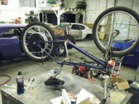
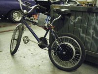
methods
1 GW
Hey - GOOD JOB!
What the hell is that?!?!
Is that a 5304 in a 20" wheel?!?
You are insane.
The controller is probably set for "full blast" so go easy on it.
If you want example settings PM me and I will email you settings that you can import.
Well that is great news!
So - here is what you do if you want to charge while still hooked up to the controller:
1) Without registering negative Ah
Basically you just put a Y connector between your battery and controller. Obvious enough.
2) If you want to charge and register AH on the CA you need to run a separate charge line out of the controller.
What you do is solder a 12AWG cable to the FET side of the shunt. This will act as your new charging ground wire.
Go ahead and also solder a 12AWG cable to somewhere on the +V rail.
Now you have 2 news lines: 1 goes directly to the Battery +V and the other has to route BACKWARDS thru the shunt to get to the Battery Ground.
Make sense?
When you charge the current will run in reverse through the shunt which will "roll back" the AH on your CA and register as a nice negative current.
As far as why you are not getting speed: Make sure the ebrake and Speed lines are not mixed up on the CA.
You are correct that you need to set it up for 12 poles. Diameter should be something in the range of 1,500mm (or whatever your tire is)
Well... I cant explain how pleased I am that you bought a couple of chargers and that you are bulk charging with alarms.
That is the way to go!
With only a 24S 1P I bet that thing charges in almost half an hour!
Good job working out the bugs.
-methods
What the hell is that?!?!
Is that a 5304 in a 20" wheel?!?
You are insane.
The controller is probably set for "full blast" so go easy on it.
If you want example settings PM me and I will email you settings that you can import.
Arlo1 said:Hey man calm down ! lol you are to funny! OK so little do you know I bought 4 bm6 moniters from HK and a 6s balancer as well I ordered two 48 volt 7.3 amp powersupplies and hooked them up in series and adjusted them up to 100.8 volts then I set my beepers on the bm6s to 3.05 which I may raise to give me sooner warning. I have charged my pack up once and stoped at 4.2 on the highest cell never knoticed it would beep at 4.22 anyways. No what I am wondering is if you just leve the pack hooked up to the bike in 100v mode and hook up the charger to another set of conectors and then charge at 100 volts but you can watch the CA because you its all still hooked up? Ok and were do I find all the settings for the program I meen I am not sure on what to put where I have some numbers and values figured out but is it the phase current that the controler limits to keep peak amps down? And you figure 30amps phase current will give me 150 total peak?
Well that is great news!
So - here is what you do if you want to charge while still hooked up to the controller:
1) Without registering negative Ah
Basically you just put a Y connector between your battery and controller. Obvious enough.
2) If you want to charge and register AH on the CA you need to run a separate charge line out of the controller.
What you do is solder a 12AWG cable to the FET side of the shunt. This will act as your new charging ground wire.
Go ahead and also solder a 12AWG cable to somewhere on the +V rail.
Now you have 2 news lines: 1 goes directly to the Battery +V and the other has to route BACKWARDS thru the shunt to get to the Battery Ground.
Make sense?
When you charge the current will run in reverse through the shunt which will "roll back" the AH on your CA and register as a nice negative current.
As far as why you are not getting speed: Make sure the ebrake and Speed lines are not mixed up on the CA.
You are correct that you need to set it up for 12 poles. Diameter should be something in the range of 1,500mm (or whatever your tire is)
Well... I cant explain how pleased I am that you bought a couple of chargers and that you are bulk charging with alarms.
That is the way to go!
With only a 24S 1P I bet that thing charges in almost half an hour!
Good job working out the bugs.
-methods
methods
1 GW
One thing - you may want to turn it down from 100.8V to more like 99.5 or something like that.
That is what I have been doing to protect for the times when I walk off and forget.
If there is not active balancing watching all 24 cells in relation to eachother then it is inevitable that at least one cell will go over 4.20V if the charger is set to 100.8V
Granted I did this for over a year but..... You may get more longevity by turning it down to 4.15V / cell.
Tell us more about the bike.
Which motor is that?
Looks awesome - my favorite ebikes are the dragsters... simple, light, and fast.
-methods
Yup simple light and fast is my goal! Thanks again methods I honestly can't quit giggling Its an x5304 I bought off of stevo. I ported it and painted it, he already drilled it out but I made it better! I got alot of work to do calibrating the sunt ect. So yeh I will be buisy and on here alot :wink: I dont think to many amps for the wheel will be a problem for it just tries to flip over backwards at anything under 20k  and this morning a car thought they should pull out infront of me because I am just a bicycle ! Hahah after there next turn I out accelerated them and left them in the dust!
Its an x5304 I bought off of stevo. I ported it and painted it, he already drilled it out but I made it better! I got alot of work to do calibrating the sunt ect. So yeh I will be buisy and on here alot :wink: I dont think to many amps for the wheel will be a problem for it just tries to flip over backwards at anything under 20k methods
1 GW
The 5304 in a 20" wheel is a great combo.
135lbs of thrust, 3kw after efficiency, and a theoretical top speed of 60mph (75mph freewheel) on 24S
Yea... A 5304 in a 20" is one hell of a performer. The only drawback is frame selection. If you try to run that setup on a Mountain Bike the pedal clearance becomes unbearable.
A BMX frame is hard on the ol'back and I imagine it is squirrely as hell after 40mph.
-methods
vanilla ice
1 MW
135mm cranks ftw!
methods
1 GW
I need those for my Stink with the 25" tires....
All my bikes scrape pedals when I lean it over
I got some serious waffle irons at the LBS for only $20 a piece!
These things have spikes coming out of them that literally grab your shoe and hold it on.
Great when hitting jumps etc.
-methods
All my bikes scrape pedals when I lean it over
I got some serious waffle irons at the LBS for only $20 a piece!
These things have spikes coming out of them that literally grab your shoe and hold it on.
Great when hitting jumps etc.
-methods
I just got clocked at 75km/h in my friends truck and it is new enough that it should be acurate. I also beet him in a drag race to 60km/h. Man to fun I am not sure at all on my settings I programed into the controler! But as for tonight I am tired so I will just do some battery ballancing and wire in my brake and try to figure out the CA. I would love to get to 60mph! Even though stevo said you can't I am realy thinking I want to figure out the WYE DELTA mode for this wheel this winter. I also don't mind the ride up to 70km it is good and still stable! I am used to hi speeds on this bike because I have alot of big hills here!
Similar threads
- Replies
- 3
- Views
- 2,253
- Replies
- 0
- Views
- 587
- Replies
- 21
- Views
- 3,264
- Replies
- 142
- Views
- 45,342
- Replies
- 28
- Views
- 9,896