JD's VW Bus Conversion EV project (2 of 2)

39178.gif
I got a GREAT 450lb tranny jack at harbor freight http://www.harborfreight.com/cpi/ctaf/displayitem.taf?Itemnumber=39178 that almost seemed designed for this task. Even better, it was $10 cheaper at the store, $79.99 plus tax.

06_trannyjack_5776.JPG
The 143lb motor is now strapped down and ready to roll!


07_ready_to%20_ack_5778.JPG
The motor on the jack was about 1" too high to slide under the bus. I was about to jack the bus up, then I tipped the motor forward on the Tranny jack's front wheels, which dipped the adaptor plate low enough to clear. Here you see the motor and the bell housing it is about to be bolted to. This motor has a tailshaft which only had a few mm clearance from the back while it was jacking up, because I also had to clear the tranny input shaft.


08_installed_5782.JPG
The Tranny jack can tilt forward, but it wasn't enough to line the input shaft up with the motor. I used a crowbar to lever up the rear of the motor so they would sort-of line up. It took a few trys to get the input shaft inserted, and even then the bottom of the adaptor plate was flush with the lip on bell housing, but there was a 1" gap at the top. I managed to get the top left bolt through and when torqued it pulled the motor flush, and I was able to get the big bolt through the top right, next to the starter. The starter made this really difficult to access the nut for this bolt, so it took a while. The bottom two bolts went in easy as pie - and I was done! Naturally, I still need a rear mount to support the motor, but this should be good enough for moving from one side of the street to the other.

I have been dreading the mechanics of installing the motor, but with the tranny jack it was a simple 1-man job. It only took about 3 hours from drilling the 4x4 to lowering the jack, I hope it is correct! Now I can focus on the electronics.

-JD

EDIT 12/14/12: replaced pictures lost when the forum crashed a few years ago.
 
Sheesh... if I'd have known any of this was even remotely doable I would have never sold my '89 Westy two years ago (needed to in order to buy a house... dumb idea in retrospect :wink: ). I miss that old beast and would have loved to electrify it. Loving this thread.. thanks for sharing!
 
I'm hugely impressed with the can ev adaptor plate. Very nice stuff, not just a cut up piece of sheet stock. And the pix on the thread are first class. Ya got us all drooling.
 
dogman said:
I'm hugely impressed with the can ev adaptor plate. Very nice stuff, not just a cut up piece of sheet stock. And the pix on the thread are first class. Ya got us all drooling.

Thanks Dogman and Pwbset! It is comments like yours that keep me wanting to post pics of my Journey with this project.

Since my last post, I heard back from Randy @ CanEv, and he said he uses threadlocker blue - so I guessed right, and thank goodness I don't have to tear it down and put in red - or have to worry about being able to get it apart at all. Important note I didn't initially put above - per the instructions there is NO threadlock on the set screws that secure the adaptor hub to the motor shaft.

At any rate, over the past two days i built a case to hold 3 rows of Headway Cells. After the batteries are in I'll put some heavier plywood on top. I started to slide the first row of 10 supercells in, then I realized I had better screw the copper ends in before dropping them all they way in. So, tomorrow I'll drill them out and finish mounting the cells I have so far... soon I should be ready to try to make it move!

-JD

tray_in_5786.JPG
 
A car conversion is in my future me thinks.. thanks for sharing great info!

J
 

Attachments

  • Pizza.jpg
    Pizza.jpg
    55.7 KB · Views: 5,016
  • rear.jpg
    rear.jpg
    67.5 KB · Views: 5,020
BTW do keep the burn marks on the rear end. Excellent theft proofing, and keep the EV labels off it too, so they don't know about all the battery money inside. The way it looks now you could park it with keys in the ignition.
 
dogman said:
The way it looks now you could park it with keys in the ignition.

You are catching on... :D

So the past two days I spent making 3 buss bars, one to join two rows of supercells, and two for the ends of the pack where I will be taking off positive and negative power. With these, I can finish assembling the battery and move onto the control system.

Each buss bar is made up of (6) 1" wide copper strips that add up to 5mm total. I''ll mount 400a silicon fuses against each of the pack-end buss bars and bolt the 4/0 cables to the fuses. I still need to cut out large holes where the end of the cells will contact the bar, small holes for the screw head, and a strip where the fuses will contact the end bars. Covering them with heatshrink and cutting holes is probably overkill, but I try to minimize exposed conductive surface to reduce the possibilities for accidental contact.

-JD
EDIT 12/14/12: replaced pictures lost when the forum crashed a few years ago.
strips1_5788.JPG
strips2_5789.JPG
 
I have always believed in alternative theft proofing. 4 huge bloodhounds at my house takes care of that, Not sure I could even tell you where the house key is. The truck gets washed at most once a year. Nobody steals what looks broken. 20 years ago a hot spring I liked to visit was plagued by native americal theives who broke into all the cars while the hippies were soaking. Mine was always untouched because of all the voodoo looking shit I kept on the dash. Nobody wanted the hex of some damn skinwalker down on their heads.
 
It took me about 6 hours today to cut holes in the buss bars' heatshrink, and finish up the 48v80ah pack (128 cells) This is twice what it took me to install the frakking motor - and now all I need is a control system and a charging system. I was not precise enough when I drilled the parallelling/charging strips, I tried to add some space for expansion and not all of the holes were the same distance. That is fine for the strips (I intended to bend the slack towards the positive terminals) but I used them as a template for the buss bars without thinking, and that caused all sorts of trouble. I wedged them in though. I had to cut grooves in the wood between the rows, to allow space for the fused charging wires.

Anyhow, below is a shot of the buss bars ready for installation, and another of the 16 supercells installed! The white cylinders sticking up are the two 400a silicon fuses, wrapped in unshrunk heatshrink (for safety), that will serve as the positive and negative terminals of the pack for the time being.. You can see 53.4v on the multimeter, I expect that will be enough to move the bus around for street cleaning while Ifinish building the rest of the systems (vacuum pump for brakes, asst safety/control/monitoring systems, etc). None of the fuseholders on the red wires have actual fuses in them, so while they look dangerous by crossing the rows, they can't short the pack.

Can anyone tell me, if I put my multimeter on the ends of an individual cell, will I read the voltage of that cell, or the voltage of the entire supercell? I only checked the cells that I added today, and I am not sure I checked all of the cells I added earlier. One of headway cells I tried to add today was discharged to 0.42v, I'll try to charge it up again but with v that low I am skeptical about its chances - I want to make sure it is the only one, but I am not ready to tear the pack down to do so. Two cells stripped their screws holes pretty easy, I figure I'll use them as end cells later with a slightly larger screw.

-JD
EDIT 12/14/12: replaced pictures lost when the forum crashed a few years ago.

strips3_5790.JPG
48v_finished_5794.JPG
 
oatnet said:
Can anyone tell me, if I put my multimeter on the ends of an individual cell, will I read the voltage of that cell, or the voltage of the entire supercell? I only checked the cells that I added today, and I am not sure I checked all of the cells I added earlier. One of headway cells I tried to add today was discharged to 0.42v, I'll try to charge it up again but with v that low I am skeptical about its chances - I want to make sure it is the only one, but I am not ready to tear the pack down to do so. Two cells stripped their screws holes pretty easy, I figure I'll use them as end cells later with a slightly larger screw.

Nice work!

Yes, you can measure the potential (voltage) across any individual cell, regardless of how it is connected to other cells. Just jump in with a multimeter.

You can also charge or discharge any individual cell in the same fashion, while connected to the others. The circuit (say the multi-meter with probes on each end of one cell) is only 'closed' around that cell, so that's all it sees.
 
voicecoils said:
Nice work!

Yes, you can measure the potential (voltage) across any individual cell, regardless of how it is connected to other cells. Just jump in with a multimeter.

You can also charge or discharge any individual cell in the same fashion, while connected to the others. The circuit (say the multi-meter with probes on each end of one cell) is only 'closed' around that cell, so that's all it sees.

Thanks voicecoils!

I am suprised about the charge/disharge though - I used to have 2 36v LiFe packs in parallel on a Tidalforce, each charged by a 36v charger/balancer (the old "Flintstone" charger if you remember them), with 13 leads so each cell had it's own individual sub-charger. When one charger died, I discovered that it was charging both packs at the same time - one via the single-cell chargers, and the other through the leads that connected them in parallel (no schotty diode). It seemed that the sum of the single-cell chargers output went up through the power leads.

-JD
 
I charged up that .42v cell today - it was on the charger for 7-8 hours, the charger never went green so I thought it was useless. Then I tested it with the CBA, and got 9.6ah from it! Maybe it never got its initial factory charge, I'll put it through a few cycles and see what I get.

A few weeks ago I mounted the controller, a kelly 600v contactor, and shunt on a wood board, and hooked up 4/0 cables for the battery and motor. This helped me think through the layout and is good enough for testing, but I will need to remount it on an aluminum plate to help drain heat from the controller, and add a 2nd contactor (ev200) on a separate circuit as an emergency disconnect.

Today I screwed (4) cells together with set-screws to make a 12v10ah "stick", mounted a waterproof fuse and on of my old ebike switchboxes to the positive side, and paralled that to the contactor and the KDH14500B's J2 connector wire 1. Then I paralleled the other side of the contactor, and J2(3). This worked like a charm and I programmed the controller. no problem. I connected a new PB6 throttle to J2(2) and J2(5), then took the whole mess downstairs, and hooked up the power cables. I wore my linesman's gloves for the battery leads, fumbling on nuts with those things was a major pain, albeit not as much of a pain as burning my arms off without them. The install is ugly, but complete, the next phase will pretty things up and make them robust enough for regular duty.

I had my wife come down to take video of the maiden voyage. The contactor clicked when I hit the power switch, I had the tranny in neutral and was braced for a runaway that never came (yay). I hit the throttle - and nothing happened. Damn. No error code on the controller, I measured correct voltage at the inputs, disconnected the microswitch, no joy. Rather than face the linesmans gloves again to unbolt everything, I brought a PC into the driveway to reprogram the controller. I made the configuration as plain Vanilla as possible, turning off high throttle etc.

The KDHB manual shows (3) choices for throttle and says "potentiometer can be used to output 0-5v". When I choose 0-5v the motor will not turn. When I choose 5-0v the motor spins full speed (thank goodness I was smart enough to have the tranny in neutral) but moving the throttle to full on does not slow motor. It is nice to hear it spin cleanly- that means everything works - but it would be nice to control it too. After powering everything down I unbolted the s2 lead so I can reconfigure the controller without spinning the motor up. In retrospect, I guess I could have just disconnected one of the contactor control leads instead.

Anyone have an idea what I am doing wrong? Here are my settings from KDHB Configuration Program:

Foot Switch: Disable
Throttle Low end dead zone: 20%
Throttle High end dead zone: 80%
Max Current: 100%
Startup Wait time: 0.5 sec
Control mode: Balanced
Under Voltage: 18v
Over Voltage :180v
Throttle up/Down rate:4
High Pedal Disable: disable
Top Speed: 100%
Half Speed on reverse: Disable
Half Current on Reverse: Disable
Motor Temperature Sensor: Disable
Stop Output Temperature: 125C
Restart Temperature: 110C

EDIT 12/14/12: replaced pictures lost when the forum crashed a few years ago.

View attachment 4
motor_5800.JPG
back of bus_5804.JPG
controller in place_5802.JPG
PB6 and 12v stick_5803.JPG
 
Its Alive!

I emailed Steven at Kelly Controller about my throttle issue. As usual, his response was quick and complete - one of the many things I like about using Kelly products.

He said that I should modify my PB6 with a third wire to 5v (J2 pin 7) to convert it a 0-5v throttle. The controller does support a 2-wire throttle, with a 1k resistor, but it is “less preferred."

So, I opened the PB6 case. I thought I was going to have to mess with the return spring to get at the pot, but that assembly remained intact. Naturally, the center connector is the wiper, and the two end connectors are the + or -. The '+' end is the open pin in the first picture, so I soldered a red wire to it. When I soldered the PB6 yesterday, I connected the black wire to ground - to me, ground is always negative.

In a resistance pot setup it the ends don't really matter, but in a 0-5v it setup it obviously does. I had a 50/50 chance of wiring it correctly, but once I opened the pot, I could see that the wiper was wired to black, and the negative side was wired to white. Rather than undo all my other work, I swapped the white and black wires at the pot (as seen in the 2nd photo). Besides being easier, it is more intuitive for me in the future.

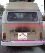
That said, I took the new control harness outside and hooked up everything but the contactor so the controller wouldn't spin the motor at power-on - I left it programmed in 5-0 mode last night. I reprogrammed the controller to 0-5 mode and re-enabled the high-pedal cutoff. The motor now responds to the throttle! I put it in reverse, gradually added the throttle, and the bus lurched backwards with far more torque than I expected for 53v, more bite than I remember from the ICE. Of course, it could well have been supplying 25kw (50vx500a), 33 electric horsepower, and the ICE was 66hp. I am eager to see how it performs on the street, but I have more to do to make it roadworthy.

Having it MOVE in a controlled fashion is a major milestone for me. To be honest, I have been stressed out about this project since I started. I have been absorbing tons of information, found out I didn't know half of what I thought I knew, and was concerned that I would miss something important or trash something or hit a roadblock beyond my skills.

The motor part really concerned me - I've never even handled a clutch or flywheel before, and if I had hit a problem (something doesn't fit, etc) I don't have the skills or tools to fix it. Ultimately the motor was the easiest part of the whole installation, everything just bolted on.

The rear-engine aircooled VW configuration compliments an electric motor installation very well, I bypassed many of the hurdles one would face converting a more modern car with a front-engine layout. I should give credit to the CanEv kit for simplifying the process too; I was considering another kit that uses a taper lock that had a lot of precision adjustments that I think were beyond my skill set, and the CanEv simply bolted on.

One must be vigilant about things including high-voltage issues, working with heavy masses, and keeping the driveline disengaged (be aware of the risks, do your homework to be safe), but with that in mind I would like to pass on to others: if you have ebikes down, converting an aircooled VW to electric is easily within your skill set. I did every single element of this conversion single handed, the only help I needed was torquing the flywheel bolts and my 5' 100lb wife helped with that. Most of the tasks here are things I never tried before.

The next step was charging. I bought (7) brand-new Vicor power supplies (as recommended by Dr. Bass - thanks for yet ANOTHER great tip Doc!). I got that many because they were new, dirt cheap, and all 8 slots filled with 48v4.2a subchargers, capable of 33.6a when paralleled! I thought these would be a nice compliment to the 48v-3.7v DC-DC converters I bought here fore single-cell chargers. I'll still use those as balancers in the future, but for now I'll charge the cells directly with one of these. The modules were all turned down to 30v, but the set screw allowed me to adjust them up to 56.2v. I tuned them to 52.8v to charge 16 cells to 3.3v/cell. By combining the 8 sub-modules in parallel and series, and adjusting set screws, I can hit any target voltage from a single charger, no matter how I configure the pack. It will only supply 1200w at 120v AC, so the higher the pack voltage the slower the charge.

So, tomorrow I hope to pump some juice into the cells, and get started on the Vacuum pump/reservoir to assist the brakes. After that, I'll mount the PB6 to the throttle cable (with a separate return spring). Then I'll work a permanent aluminum-plate mounting for the controller and the Jumbo-Screen Cycleanalyst I've had in storage. Then this will be ready for basic road testing to see how many watts/mile this uses to size the final battery pack. Then I am ready for the final, permanent install of all systems.

But today, today it moves!

-JD

NOTE: THESE ARE THE RAMBLINGS OF A RANK AMATEUR ON HIS FIRST EV CONVERSION JOURNEY - LISTEN AT YOUR OWN PERIL.

pb6_before_5805.JPG
View attachment 1
vicorama_5810.JPG
 
Kudos!

(Safety tip: If this is your first EV-auto, it is very easy to forget the vehicle is turned on; since there is no engine noise, no idle... your parking brake can help keep your garage-wall (or other cars/people) intact.)

It might even seem a bit freaky to drive bus that's quiet for the first couple of months.
 
Wow.. watta nice project!! :D

Glad to hear you are satisfied with the current results!! You have the chance that i have not from now.. building an Electric car!.. I dont have the rigt garage and $$ from now.. but with the bayttery sales, that help!! :wink:


Please continu to share this with us!!
Doc
 
This is quite an accomplishment. Great job. :)

Curious on the charger settings, though. You mentioned you are charging each block of cells to 3.3V, which is the nominal voltage for LiFePO4 cells, but to get a full charge, you need to go to at least 3.65V per cell and then let the current taper off.

-- Gary
 
Wow!

Thanks for the good words everyone!

Dogman, the most frequent poster, thanks for your words of encouragment all the way through, hope you'll keep with me the rest of the way.
TD, I was thinking about your post, and wondering if I should have a recording (like the Jetson's car) that plays when the car is powered on but not moving. Thanks for the advice!
pwbset, video is coming - I wanted a "maiden voyage" vid but it was too dark... But soon...
Doc, I know when you get around to building an e-car, it will be superb. There are probably a dozen tips I learned from your posts integrated into my setup (see below too), so thank YOU!

GGoodrum said:
This is quite an accomplishment. Great job. :)
Curious on the charger settings, though. You mentioned you are charging each block of cells to 3.3V, which is the nominal voltage for LiFePO4 cells, but to get a full charge, you need to go to at least 3.65V per cell and then let the current taper off.
-- Gary

Gary, you are right on point - I was coming here to post for advice on how to configure the PSU. My experience to date has been to use single-cell chargers, typically about 3.7-3.75v, that were designed for a LiFePO4 charge cycle.

Recently I saw a post from DoctorBass talking about charging to a lower voltage to preserve battery life. I can't find that post now Doc, but I seem to remember you were saying that not adding that peak charge - that 1% that I burn off on my ebikes in 10 seconds anyhow- it will extend cycle life. I like the idea!

I was thinking my 24s 72v LiFePO4 packs typically rest @79v-80v when that peak charge burned off, @3.3v/cell, so that was my target. Today I thought maybe I should exceed that a little bit just to make sure they are taking a reasonably full charge. Then I thought maybe I don't know enough about charging with a PSU.

I remember xyster (we still miss you X-Man) used to charge his Lipo with 4.2v PSUs, saying that once the battery reached 4.2v it would not accept any more current, asserting that his charging setup was intrinsically safe (contrary to the way it looked in the photos :p ). That is what I was going for with this setup, and maybe backing it up with a timer. SO, here are my questions:

1) Will the pack stop accepting current when it reaches PSU voltage?

2) If no to #1), and I don't taper down the current, will that be incrementally damaging to the chemistry?

3) If yes to #1), I set the PSU for 3.4v/3.5v per cell, what is their likely state of balance when they reach PSU voltage? If that peak charge between 3.3v and 3.65v is 1% of capacity (estimated from CBA tests over the years), then wouldn't all cells be @ 99% of capacity when charged to 3.4v, and roughly balanced?

Wait. No. Crap. Some supercells could be at 3.75v, and some at a 3.25v, and still average 3.50v... Duh. I must be tired.

OTOH, if I periodically balance the supercells with the Vicor 48v-3.7v dc-dc convertors (trimmed) I got from powermed last fall (
http://endless-sphere.com/forums/viewtopic.php?f=9&t=7392&p=111974&hilit=vicor#p111974 ), then maybe they WILL balance to that 99% range...

-JD
 
marks said:
Just curiously, could you use all that spare space on either side of the electric motor for more batteries?

Hi marks!

There is a TON of space that others have used with Pba cells, as this recent 1973 vw Bus conversion demontrates:
(NOTE: THIS IS NOT MY BUS, IT IS SOMEONE ELSES)

[youtube]KAC13Jx4gkA[/youtube]

However, just like on an ebike, that puts weight behind the axle, and would accentuate the tendancy for the front of VW buses to bob up and down. As a rear-engine/transmissioned vehicle, it is closer to 75/25 than the ideal 50/50 front rear weight distribution. The chamber for the removed gas tank is right over the axles, so when I determine the pack size, if it will fit in there that is an ideal, protected spot for them. OTOH, with the cells in their current temporary location it gets me closer to that 50/50. It also gives me easy access for fiddling about with them.

I have also considered having a box built to mounti them UNDER the floor of the bus - I was thinking about this location when I was considering converting it with lead-acid 3-4 years ago, and just recently recalled it. There is a lot of ground clearance (she is a breeze to work under), and the three steel beams that run the length of the bus are excellent mounting points. Heck, I think that space is 3" high, so the 1.5" cells would be invisible - with only the motor and controller visible, that would be nice clean looking install.

Ah, it will be nice to make this installation pretty instead of just functional, but I have a lot to learn and do before I get there. :oops: :D

-JD
 
Looks great keep the reports coming

What is the finale volts and Ah are you going to use and what speed and range do you hope to get?

Mark
 
markcycle said:
Looks great keep the reports coming
What is the finale volts and Ah are you going to use and what speed and range do you hope to get?
Mark

Hi Mark!

Good questions, but I only have vague answers. I know you have a lot of experience so I'd really like to hear what you think I'll need.

The bus is a large vehicle designed to work with a small (66hp) motor, so I think it is different from other large conversions. It is a brick, but it is an rounded, slab-sided brick, so drag is difficult to estimate. While lots of people have converted them with Lead Acid (adding 1500lbs), I don't know of any other LiFePO4 bus conversions (keeping weight under stock), so I don't have documented experiences to baseline how big a pack should be. I have seen claims of 300-350wpm on much heavier lead-acid conversions.

My base goal is pretty easy:
a) It will be a roaring success if I can do my 16 mile daily commute at 45mph, accellerate faster than the old ICE, and weigh less than stock.

That said:
b) It will be more versatile if I can get 30-35 miles miles out of it at 45mph, any more is gravy.
c) It would be nice to have it freeway capable with enough kwh to still have usable range, but i rarely drive the freeway so I don't really need that and I want to keep the weight down. The 66hp ICE moved it @ 65-75 depending on prevailing winds. It would take 50kw (750w=1hp for those who didn't know) to equal the 66hp ICE, but I keep reading that less electrical HP equals ICE HP because they are measured differently. I am eager to see how they compare.

AH: The pack is currently sized at 80ah to yield a factory-rated 400a. Steven of Kelly Controllers reports that my 500a controller will never consume more than 400a so I specced to that. Real-world testing will tell me how much the controller pulls, and how well the cells perform under that load, and maybe AH will change.

V: The controller is good up to 180v, peak output of 90kw :shock: . The battery box I built will hold 90v of supercells, I could put another battery box on top of that to hold 180v if need be. I only have 48v now (the pack was originally intended for my Comuta-Car project), I plan to add more cells in series to up the voltage (and kw in the pack) to meet goal a, probably goal b, and maybe even c. Once I get it beyond moving and truly roadworthy, I'll do some test runs over local routes to see how many wpm it consumes, and then I'll have a better idea of target voltage. I was really suprised how much pull it had in my simple driveway test yesterday, with a mere 48v.

For example, I am thinking that a 90v80ah pack at 80% DOD would yield 5.760 kwh, enough to do my 16 mile commute at 360wpm. I think it would be sweet if, by keeping weight down with LiFePO4, I can get under 250wpm at 45mph.

I'd like to continue with the Headway cells, but I see the Thundersky large-format cells are broaching $1.50/ah (ebay:junglemotors) so I might mix and match depending on what Victoria can do with her pricing. The funny thing is, when I first researched doing the conversion with T-Skys, $1.50/ah was the price point where conversion made sense; now I have done the conversion and need batteries they are at just the right price.

Anyhow, all those unanswered questions are why everything is so temporary-looking and the current battery box is so crude. Heck, I might find that the 500a peak controller - rated at 450a 1-minute, but only 200a continious - is not up to my needs. So for now it is a rolling test-bed and learning lab.

-JD
 
Thank you, JD, for your thorough posts. I've really enjoyed reading this thread. You almost make the conversion look easy.
Two simple questions:
Have you considered the potential need for battery (or motor) cooling?
Are you going to include a rain or dust shield underneath the motor?

Eric
 
JD --

All Lithium-based cells, and SLAs, for that matter, charge the same way. The charger/supply starts off pumping out as much current as it can (constant current mode...). As the cell becomes fuller, it becomes harder for the cell to accept current at the same level, so the voltage starts to rise, at a steady rate. When the cell gets to about the 85% level, the voltage starts to rise at a faster rate. For LiFePO4 cells, this point where the voltage starts to rise faster is at about 3.65-3.70V. For LiCo (LiPo...) and LiMN (Konion/eMoli...), it is 4.20V and for SLAs it is around 2.40-2.45V. In order to get the last 10-15% into the cell, the charger/supply just needs to limit the voltage once it gets to this crossover point. This is called the constant voltage (CV) mode. What happens is that since the voltage can't rise any more, the cell starts to reduce the current it can let in. Once the current drops under about 50-100mA, the cell is about as full as it is going to get.

Your 3.7V/4.2A supplies are basically already individual cell CC/CV chargers. They will start out limiting the current to 4.2A, until the voltage gets up to the set point, and then it switches to the CV mode and limits the voltage. If you don't want to do a full charge, what you could do is simply shut off the charge when the cells get to the crossover point (3.65-3.70V). Personally, I don't think it is a good idea to not fully charge the cells. I think not discharging below a level like 20-30% is probably good for some extra life, but not charging all the way is not good, in my mind, as it is too easy to get cells out-of-balance doing this.

-- Gary
 
Back
Top