
You are using an out of date browser. It may not display this or other websites correctly.
You should upgrade or use an alternative browser.
You should upgrade or use an alternative browser.
JP spot-welder, FET-switched, timed adj. pulse
- Thread starter okashira
- Start date
grip911 said:Does anybody on this forum know how to fix these welders. I just blew mine up again. Managed to get in 6000 welds.
Replace the output mosfets, 99% chance that they are the only component that blew.
Managed to get in 6000 welds
Thats a great record for the basic model (easy and cheap to fix), but...if it can be completely bombproof for another $20, I'd like to know what the "deluxe" version would be like.
Would putting paste in between the mosfets and the aluminum bar ,help in keeping the fets cooler?riba2233 said:Yeah, they can make pop soundBut sometimes they die quietly, without noise.
Alan B
100 GW
The events that damage the FETs don't give time for heat to flow.
flangefrog
1 kW
I know this has been explained before (e.g. by Tesseract) but here's my attempt to simplify it a bit for the less technically inclined. Please correct me if I've got anything wrong. Oscilloscope image is from okashira.
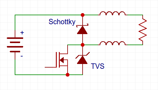
The standard spot welder looks like the above circuit but without the two diodes. There's a battery on the left and the mosfets are on the bottom. The probe wires coming from the positive terminal of the battery and the drain of the mosfet are shown on the right by the two inductors and the small resistance of the nickel and probe contacts is shown by the resistor. The wires' inductance depends on their length.
The mosfets have a VDSS (Drain-Source Breakdown Voltage) rating. This means that if the difference in potential (voltage) between the drain and source pins is higher than the VDSS then they will pass current even when switched off and may be destroyed. The fets are rated conservatively so in practice the voltage actually has to be a bit above the VDSS to pass through.
The problem with the wire inductance is that inductors store energy and resist changes in current flow. When the mosfets are suddenly turned off, the inductor wants to keep that current flowing, so the voltage rises until it is high enough to pass through the mosfet. When using a 24V rated mosfet the actual VDSS is about 30V. If the current pulse was 2000A and the original voltage was 13V then the current flowing through the mosfet will be 866A. The power (A x V) will be the same. The current will continue to flow through the mosfet until all the power stored in the wires has dissipated as heat (mostly through the fet itself). This pulse through the mosfet when it is switched off is called avalanche.
Mosfets can handle a certain amount of avalanche. You can find the specs under IAR (Avalanche Current), EAS (Single Pulse Avalanche Energy) and EAR (Repetitive Avalanche Energy) in the datasheet. When you are not welding with too high voltage or current the avalanche energy may be above those limits but not so high as to significantly reduce the lifespan.
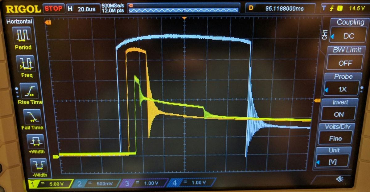
In the blue trace above you can see the voltage across the mosfet (VDS) in a circuit with no protection diodes. All the energy stored in the wires inductance is released through the mosfet. As the mosfet's VDSS rating is just above the yellow trace, this means the mosfet is avalanching for 110 microseconds.
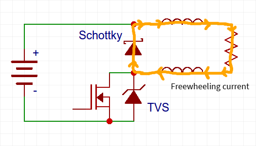
In the second orange trace, a schottky diode as been added as per the above schematic. This gives a much easier path for the current to flow through when the mosfet is turned off. Practically all of the energy from the wires is now flowing through the schottky diode (which is called a freewheeling diode when used in this way) instead of the mosfets.
Current path of inductive energy stored in probe wires:
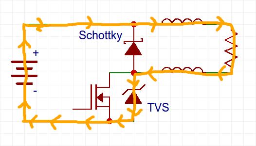
The voltage is still high enough above the mosfet's VDSS to avalanche for 20 microseconds. Why is that? There is also inductance on the left side of the circuit - the battery, possibly a short lead to the spot welder and the length of wire between the battery and the Schottky cathode (which is why the cathode should be attached directly to the battery, not half way along the probe wire). As the wires or bus bars not too long and the battery doesn't have too high inductance, the inductance is much lower than the probe wires. It's still enough to cause a bit of avalanche though.
The voltage of the first two traces is a bit different. Shouldn't they be clamped to just above the VDSS because all the current starts passing thorough once the voltage is above that? There's still a bit of resistance in the mosfet. This means that even though some current might start passing through at just above the VDSS, when more current is flowing the voltage will get higher.
In the third yellow trace, a TVS (Transient Voltage Suppressor) diode has been added. This is a special type of diode that starts passing some current when the voltage is above it's VBR (Breakdown Voltage). It's also called an avalanche diode. We choose a TVS that has a VCL (Clamping Voltage) of less than the mosfet's VDSS. The clamping voltage is the voltage where the diode will turn fully on. When placed across the mosfets as in the schematic, the inductive energy stored on the battery side is released and takes the following path:
In the yellow oscilloscope trace the mosfet voltage never gets above the VDSS so there is no avalanche. Now the mosfets will last much longer!
The standard spot welder looks like the above circuit but without the two diodes. There's a battery on the left and the mosfets are on the bottom. The probe wires coming from the positive terminal of the battery and the drain of the mosfet are shown on the right by the two inductors and the small resistance of the nickel and probe contacts is shown by the resistor. The wires' inductance depends on their length.
The mosfets have a VDSS (Drain-Source Breakdown Voltage) rating. This means that if the difference in potential (voltage) between the drain and source pins is higher than the VDSS then they will pass current even when switched off and may be destroyed. The fets are rated conservatively so in practice the voltage actually has to be a bit above the VDSS to pass through.
The problem with the wire inductance is that inductors store energy and resist changes in current flow. When the mosfets are suddenly turned off, the inductor wants to keep that current flowing, so the voltage rises until it is high enough to pass through the mosfet. When using a 24V rated mosfet the actual VDSS is about 30V. If the current pulse was 2000A and the original voltage was 13V then the current flowing through the mosfet will be 866A. The power (A x V) will be the same. The current will continue to flow through the mosfet until all the power stored in the wires has dissipated as heat (mostly through the fet itself). This pulse through the mosfet when it is switched off is called avalanche.
Mosfets can handle a certain amount of avalanche. You can find the specs under IAR (Avalanche Current), EAS (Single Pulse Avalanche Energy) and EAR (Repetitive Avalanche Energy) in the datasheet. When you are not welding with too high voltage or current the avalanche energy may be above those limits but not so high as to significantly reduce the lifespan.
In the blue trace above you can see the voltage across the mosfet (VDS) in a circuit with no protection diodes. All the energy stored in the wires inductance is released through the mosfet. As the mosfet's VDSS rating is just above the yellow trace, this means the mosfet is avalanching for 110 microseconds.
In the second orange trace, a schottky diode as been added as per the above schematic. This gives a much easier path for the current to flow through when the mosfet is turned off. Practically all of the energy from the wires is now flowing through the schottky diode (which is called a freewheeling diode when used in this way) instead of the mosfets.
Current path of inductive energy stored in probe wires:
The voltage is still high enough above the mosfet's VDSS to avalanche for 20 microseconds. Why is that? There is also inductance on the left side of the circuit - the battery, possibly a short lead to the spot welder and the length of wire between the battery and the Schottky cathode (which is why the cathode should be attached directly to the battery, not half way along the probe wire). As the wires or bus bars not too long and the battery doesn't have too high inductance, the inductance is much lower than the probe wires. It's still enough to cause a bit of avalanche though.
The voltage of the first two traces is a bit different. Shouldn't they be clamped to just above the VDSS because all the current starts passing thorough once the voltage is above that? There's still a bit of resistance in the mosfet. This means that even though some current might start passing through at just above the VDSS, when more current is flowing the voltage will get higher.
In the third yellow trace, a TVS (Transient Voltage Suppressor) diode has been added. This is a special type of diode that starts passing some current when the voltage is above it's VBR (Breakdown Voltage). It's also called an avalanche diode. We choose a TVS that has a VCL (Clamping Voltage) of less than the mosfet's VDSS. The clamping voltage is the voltage where the diode will turn fully on. When placed across the mosfets as in the schematic, the inductive energy stored on the battery side is released and takes the following path:
In the yellow oscilloscope trace the mosfet voltage never gets above the VDSS so there is no avalanche. Now the mosfets will last much longer!
Thank you very much. I appreciate you taking the time to post all of that info.
Yes, great drawing. Thanks for posting it.
A capacitor from the FET source to the top of the freewheel diode might help, but lead lengths will cause inductance.
A capacitor from the FET source to the top of the freewheel diode might help, but lead lengths will cause inductance.
Changed the fets , and welder still did not work. Lifted the aluminum bar and discovered 4 of the 6 traces were gone or cracked. put a bit of solder to bridge and after checking continuity VOILA! back in business.I forget who mentioned to check underneath the bar, but it was a good pointer.grip911 said:riba2233 said:Yeah, they can make pop sound
okashira
10 kW
flangefrog said:I know this has been explained before (e.g. by Tesseract) but here's my attempt to simplify it a bit for the less technically inclined. Please correct me if I've got anything wrong. Oscilloscope image is from okashira.
The standard spot welder looks like the above circuit but without the two diodes. There's a battery on the left and the mosfets are on the bottom. The probe wires coming from the positive terminal of the battery and the drain of the mosfet are shown on the right by the two inductors and the small resistance of the nickel and probe contacts is shown by the resistor. The wires' inductance depends on their length.
The mosfets have a VDSS (Drain-Source Breakdown Voltage) rating. This means that if the difference in potential (voltage) between the drain and source pins is higher than the VDSS then they will pass current even when switched off and may be destroyed. The fets are rated conservatively so in practice the voltage actually has to be a bit above the VDSS to pass through.
The problem with the wire inductance is that inductors store energy and resist changes in current flow. When the mosfets are suddenly turned off, the inductor wants to keep that current flowing, so the voltage rises until it is high enough to pass through the mosfet. When using a 24V rated mosfet the actual VDSS is about 30V. If the current pulse was 2000A and the original voltage was 13V then the current flowing through the mosfet will be 866A. The power (A x V) will be the same. The current will continue to flow through the mosfet until all the power stored in the wires has dissipated as heat (mostly through the fet itself). This pulse through the mosfet when it is switched off is called avalanche.
Mosfets can handle a certain amount of avalanche. You can find the specs under IAR (Avalanche Current), EAS (Single Pulse Avalanche Energy) and EAR (Repetitive Avalanche Energy) in the datasheet. When you are not welding with too high voltage or current the avalanche energy may be above those limits but not so high as to significantly reduce the lifespan.
In the blue trace above you can see the voltage across the mosfet (VDS) in a circuit with no protection diodes. All the energy stored in the wires inductance is released through the mosfet. As the mosfet's VDSS rating is just above the yellow trace, this means the mosfet is avalanching for 110 microseconds.
In the second orange trace, a schottky diode as been added as per the above schematic. This gives a much easier path for the current to flow through when the mosfet is turned off. Practically all of the energy from the wires is now flowing through the schottky diode (which is called a freewheeling diode when used in this way) instead of the mosfets.
Current path of inductive energy stored in probe wires:
The voltage is still high enough above the mosfet's VDSS to avalanche for 20 microseconds. Why is that? There is also inductance on the left side of the circuit - the battery, possibly a short lead to the spot welder and the length of wire between the battery and the Schottky cathode (which is why the cathode should be attached directly to the battery, not half way along the probe wire). As the wires or bus bars not too long and the battery doesn't have too high inductance, the inductance is much lower than the probe wires. It's still enough to cause a bit of avalanche though.
The voltage of the first two traces is a bit different. Shouldn't they be clamped to just above the VDSS because all the current starts passing thorough once the voltage is above that? There's still a bit of resistance in the mosfet. This means that even though some current might start passing through at just above the VDSS, when more current is flowing the voltage will get higher.
In the third yellow trace, a TVS (Transient Voltage Suppressor) diode has been added. This is a special type of diode that starts passing some current when the voltage is above it's VBR (Breakdown Voltage). It's a type of zener diode. We choose a TVS that has a VCL (Clamping Voltage) of less than the mosfet's VDSS. The clamping voltage is the voltage where the diode will turn fully on. When placed across the mosfets as in the schematic, the inductive energy stored on the battery side is released and takes the following path:
In the yellow oscilloscope trace the mosfet voltage never gets above the VDSS so there is no avalanche. Now the mosfets will last much longer!
Thanks for the better organized way of explainng what I already tried to do.
The TVS diode works because it's inductance path is very low compared to the flyback circuit.
The flyback takes care of 90% of the avalanche energy. The TVS takes care of 9% more. This puts the FET"s well within their avalanche ratings.
pguk
100 W
It took me a while for the penny to drop re my understanding of avalanche. Your explanation is well taken. That flat top of the blue & orange traces is when the voltage goes no higher *because* current is finally forced through the FET. I had hoped to avoid extra components by using devices which would be like a brick wall to the inductive effect, but it seems this current has to go somewhere: if not thro a flyback diode then it will force its way through those FETs.
An excellent summary, thank you for taking the time.
An excellent summary, thank you for taking the time.
Pompecukor
1 mW
- Joined
- Apr 23, 2016
- Messages
- 11
flangefrog said:I know this has been explained before (e.g. by Tesseract) but here's my attempt to simplify it a bit for the less technically inclined. Please correct me if I've got anything wrong. Oscilloscope image is from okashira.
The standard spot welder looks like the above circuit but without the two diodes. There's a battery on the left and the mosfets are on the bottom. The probe wires coming from the positive terminal of the battery and the drain of the mosfet are shown on the right by the two inductors and the small resistance of the nickel and probe contacts is shown by the resistor. The wires' inductance depends on their length.
The mosfets have a VDSS (Drain-Source Breakdown Voltage) rating. This means that if the difference in potential (voltage) between the drain and source pins is higher than the VDSS then they will pass current even when switched off and may be destroyed. The fets are rated conservatively so in practice the voltage actually has to be a bit above the VDSS to pass through.
The problem with the wire inductance is that inductors store energy and resist changes in current flow. When the mosfets are suddenly turned off, the inductor wants to keep that current flowing, so the voltage rises until it is high enough to pass through the mosfet. When using a 24V rated mosfet the actual VDSS is about 30V. If the current pulse was 2000A and the original voltage was 13V then the current flowing through the mosfet will be 866A. The power (A x V) will be the same. The current will continue to flow through the mosfet until all the power stored in the wires has dissipated as heat (mostly through the fet itself). This pulse through the mosfet when it is switched off is called avalanche.
Mosfets can handle a certain amount of avalanche. You can find the specs under IAR (Avalanche Current), EAS (Single Pulse Avalanche Energy) and EAR (Repetitive Avalanche Energy) in the datasheet. When you are not welding with too high voltage or current the avalanche energy may be above those limits but not so high as to significantly reduce the lifespan.
In the blue trace above you can see the voltage across the mosfet (VDS) in a circuit with no protection diodes. All the energy stored in the wires inductance is released through the mosfet. As the mosfet's VDSS rating is just above the yellow trace, this means the mosfet is avalanching for 110 microseconds.
In the second orange trace, a schottky diode as been added as per the above schematic. This gives a much easier path for the current to flow through when the mosfet is turned off. Practically all of the energy from the wires is now flowing through the schottky diode (which is called a freewheeling diode when used in this way) instead of the mosfets.
Current path of inductive energy stored in probe wires:
The voltage is still high enough above the mosfet's VDSS to avalanche for 20 microseconds. Why is that? There is also inductance on the left side of the circuit - the battery, possibly a short lead to the spot welder and the length of wire between the battery and the Schottky cathode (which is why the cathode should be attached directly to the battery, not half way along the probe wire). As the wires or bus bars not too long and the battery doesn't have too high inductance, the inductance is much lower than the probe wires. It's still enough to cause a bit of avalanche though.
The voltage of the first two traces is a bit different. Shouldn't they be clamped to just above the VDSS because all the current starts passing thorough once the voltage is above that? There's still a bit of resistance in the mosfet. This means that even though some current might start passing through at just above the VDSS, when more current is flowing the voltage will get higher.
In the third yellow trace, a TVS (Transient Voltage Suppressor) diode has been added. This is a special type of diode that starts passing some current when the voltage is above it's VBR (Breakdown Voltage). It's a type of zener diode. We choose a TVS that has a VCL (Clamping Voltage) of less than the mosfet's VDSS. The clamping voltage is the voltage where the diode will turn fully on. When placed across the mosfets as in the schematic, the inductive energy stored on the battery side is released and takes the following path:
In the yellow oscilloscope trace the mosfet voltage never gets above the VDSS[7/size] so there is no avalanche. Now the mosfets will last much longer!
Could somebody be nice enough to link me (for example from here Reichelt.de) the exact two diodes needed. If I put just the name I get an overwhelming list
I don't know what parameters are needed. Thank you.
flangefrog
1 kW
These are the diodes I have bought for a 12V lead acid battery. I can't find them on reichelt.de but you could search on octopart or find one with these specs: https://endless-sphere.com/forums/viewtopic.php?f=14&t=81400&start=500#p1208273Pompecukor said:Could somebody be nice enough to link me (for example from here Reichelt.de) the exact two diodes needed. If I put just the name I get an overwhelming list
Thank you.
Vishay Semiconductors VS-100BGQ015 Schottky Diode
Vishay Semiconductors 5KP14A-E3/54 TVS Diode
You could also use some fets instead of the schottky diode but I don't know if they will work as well: https://endless-sphere.com/forums/viewtopic.php?f=14&t=81400&start=50#p1152923
Edit: These are the best I could find at reichelt.de. I'm not sure if the schottky or epitaxial diode is better. Probably the schottky as you can buy more for the same price. You may need several diodes in parallel. Since you're using a long battery cable, I'm guessing you have the spot welder nearer the probes end. In that case your TVS diodes will get hotter. It would be better to keep the spot welder as close to the battery as possible so the schottky/epitaxial diodes can do most of the work.
MBR 4045PT Schottky diode
DSEI 60-06A Fast recovery epitaxial diode
1N6275A TVS Diode
Pompecukor
1 mW
- Joined
- Apr 23, 2016
- Messages
- 11
flangefrog said:These are the diodes I have bought for a 12V lead acid battery. I can't find them on reichelt.de but you could search on octopart or find one with these specs: https://endless-sphere.com/forums/viewtopic.php?f=14&t=81400&start=500#p1208273Pompecukor said:Could somebody be nice enough to link me (for example from here Reichelt.de) the exact two diodes needed. If I put just the name I get an overwhelming list
Thank you.
Vishay Semiconductors VS-100BGQ015 Schottky Diode
Vishay Semiconductors 5KP14A-E3/54 TVS Diode
You could also use some fets instead of the schottky diode but I don't know if they will work as well: https://endless-sphere.com/forums/viewtopic.php?f=14&t=81400&start=50#p1152923
Edit: These are the best I could find at reichelt.de. I'm not sure if the schottky or epitaxial diode is better. Probably the schottky as you can buy more for the same price. You may need several diodes in parallel. Since you're using a long battery cable, I'm guessing you have the spot welder nearer the probes end. In that case your TVS diodes will get hotter. It would be better to keep the spot welder as close to the battery as possible so the schottky/epitaxial diodes can do most of the work.
MBR 4045PT Schottky diode
DSEI 60-06A Fast recovery epitaxial diode
1N6275A TVS Diode
Thank you so much. I will shorten the cable and put the battery right next to me. Also Inwill get a smaller battery (50A).
You said I need to buy more and put in parallel. How many exactly? Thank you.
flangefrog
1 kW
I think two schottky and three TVS diodes would be the max you need. Even just one of each or only a schottky will help.Pompecukor said:flangefrog said:Pompecukor said:Thank you so much. I will shorten the cable and put the battery right next to me. Also Inwill get a smaller battery (50A).
You said I need to buy more and put in parallel. How many exactly? Thank you.
Pompecukor
1 mW
- Joined
- Apr 23, 2016
- Messages
- 11
And all in parallel right, tvs too?
flangefrog
1 kW
The schottky diodes would need to be in parallel with each other, and the TVS diodes in parallel with each other. They are both installed in different locations.Pompecukor said:And all in parallel right, tvs too?
sl33py
10 kW
Is it possible to show the TVS and Schottky installed? I get it helps, but not sure where it's at here.
Thx!
Thx!
Pompecukor
1 mW
- Joined
- Apr 23, 2016
- Messages
- 11
flangefrog said:The schottky diodes would need to be in parallel with each other, and the TVS diodes in parallel with each other. They are both installed in different locations.Pompecukor said:And all in parallel right, tvs too?
You have been such a great help thank you so much. It's so nice that you help people out here in your private time. I appreciate it a lot.
Do you think I should get a smaller battery too?
Similar threads
- Replies
- 8
- Views
- 566
- Replies
- 23
- Views
- 2,321
- Replies
- 2
- Views
- 774
- Replies
- 15
- Views
- 10,307