Just been given this

NeilP said:
, but neither thread goes in to detail on how to split the ring gear off or get the rotor out.

I'll have to take pictures my self and rectify this as soon as I strip mine.

Doh..yes sorry, I missed it, the Pedelecs link Jeremy gave me does link to those pictures Jeremy re posted for me...my fault for not reading th ethread properly ans seeing there was more than one page..I blame my eyes :shock: and the fact I was reading on an iphone. That is my excuse and I am sticking to it
 
NeilP said:
Doh..yes sorry, I missed it, the Pedelecs link Jeremy gave me does link to those pictures Jeremy re posted for me...my fault for not reading th ethread properly ans seeing there was more than one page..I blame my eyes :shock: and the fact I was reading on an iphone. That is my excuse and I am sticking to it

It does slightly worry me when pilot blames his eyesight........... :roll:
 
Jeremy Harris said:
NeilP said:
Doh..yes sorry, I missed it, the Pedelecs link Jeremy gave me does link to those pictures Jeremy re posted for me...my fault for not reading th ethread properly ans seeing there was more than one page..I blame my eyes :shock: and the fact I was reading on an iphone. That is my excuse and I am sticking to it

It does slightly worry me when pilot blames his eyesight........... :roll:

LOL...
 
I found out how the ring comes off one of these, slightly different to the others, the ring gear seems to come off with the planets, after removing the bearing roller pins.

Just levered it off with a pair of screw drivers/levers.

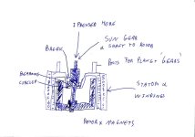
I then presed the rotor out. that is where it all went wrong. There does not seem to be a way to strip it without first drilling and tapping the rotor. The way I did I pressed it, the housing cracked and came away with the bearing and shaft. Nearing was held in with circlip that was in no way accessible. But of course you can only see that once it is too late. The rotor needs to be pulled out rather like the way one removes a brake drum on a car.

Crap design though, becaise if I had first pressed out the shaft,there is no way to them grab the rotor to withdraw it. It needs some holes drilled and tapped in to it to allow a puller to remove it

Rotor and magnets were all secure, but corroded, so I guess the noise was just tight clearance between stator and rotor and the corosion rubbing

probably scrapped a perfectly good motor, that with a good spray with WD40 and a high speed run would have cleaned itself
although the cracked off portion is a very good fit back in the housing, so possible a roughing of the edges and then filling the surrounsing cavity with DP420 may make a repair

Will try in the morning if I dont get called to work

fr_14_size640[1].jpg
fr_16_size640[1].jpg
fr_17_size640[1].jpg
View attachment 1
 

Attachments

  • fr_19_size640[1].jpg
    fr_19_size640[1].jpg
    56.7 KB · Views: 1,411
On looking at rotor a second time, it appears magnets are loose.
There are 4 of them, and the glue has failed on three, so I guess they are dragging when it spins up.
I'll glue it all back together, solder some new wire on and see what happens
This all relies on being able to get the bearing carrier glued back in square of course. It seems to locate in spot on, but, only one way to find out
 
Got it built back up

Shoudl a motor like this with only 4 magnets run with a standard BLDC controller?

I am not planning on taking it apart again, so does anyone reckon there is some sort of cut out / auto res set fuse or similar built in to the windings. I know for sure there is nothing like that as part of the hall sensors, as I fitted new thinner wires and a new sensor.

Both phase and halls ceheck out on the Lyen tester, and controller happily runs another motor.

But what happens ( and this happend with the original controller too) .. si that it runs, seems ok, if you open the throttle two or three times..leave it go for 2 or 3 minutes, and all is fine. Open throttle, close, open close, and eventually the motor starts to cut out..it won't spin up when throttel is opened. Whenthi happens, I have then switched the controller to another motor, also bench mounted, and it runs fine.

I will try a sensorless controler next
 
ok, WELL SENSORLESS CONTROLLER WORKED FINE, SO TIMING ISSUE, MANAGED TO GET IT RUNNING ok fuckin g caps lock

got it running with the sensored controller but very high current.
took it apart again, and foudn the hall PCB hgad slipped...sorry, for typos...in workshop with keyboard with no marking on it, soi a lot of touch typing to find the keys..

Have been here now since 0630 popped in to workshop before breakfast..and never left..not eaten yet today had only two cups of coffee...it is now 1630...and I am beginning to get very ratty ..irrate and annoyed...but I cnat give up gotta see it run..and the worst of it all...I do not plan on usuing this motor anyway.....shoudl be doing countless other jobs, but no f in garoudn with something I do not need..

Aggghh sorry to rant..
 
Rant away.......

That last post was pretty hilarious, BTW, I've lost count of the days lost doing stuff just like that.
 
Feeling better now.
got it going jsut now...It took over an hour to heat shrink and gt the wires back through the axle...I should have spliced them inside the motor...not where they enter the shaft..but I was not going to take the £^$*$& thing apart again to do them.

Youtube video uploading now

just finished my coffee my mate made me at 1500hrs

http://youtu.be/VTieDRIfpT8


[youtube]VTieDRIfpT8[/youtube]
 
Stupid more like...you know what it is like...that feeling of just getting one thing done. I only popped in to workshop to glue the bit that I broke the day before, with plans to go and do something else...but it jsut sort of snowballed.. No food all day just two coffees, and I coudl feel myself getting more and more irrate as the day went on and blood sugar levels started to drop.
If I had not been such a muppet and pressed the casing in half, then I would not have had to fix it...Well it had to come apart anyway, to fix the magnets,


This is more for anyone else and future reference if they need to take one apart.

I pressed from the top, guessing that the there must be a bearing inside and that it would all press out in one with the shaft and rotor...WRONG :cry:

The casing cracked and only then was the construction method visible.

What one would need to do is first is drill the top of the rotor in two or three places, tap the holes and then use a puller to remove the rotor from the shaft. Maybe you could drive the shaft/sun gear out first from the rotor side. This may then give access through the bearing to somehow push the rotor out against the magnetic forces, but I am not sure you would do it.
Another possibility is to see if the pins that support the planets can be pulled out from the 'gearbox' side, which would allow pressing of the rotor out from that side with three pins. But I am guessing those posts are just a press fit in the casing and not going to be that easy to get out from that side

IMG.jpg
 
Unlike other versions of this motor, you cant access the halls through a hole in the side cover. Cover has to come off.
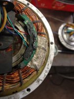
Remove the shaft, feed the wires through and the 4 screws holding the plastic centre section before removing the aluminium cover. This will leave the plastic sections and hall board in place on two little plastic clips, which I did not notice on first assembly. I tried to locate the hall sensor board in the cut out in the side case. This resulted in not beign able to get the motor to spin at a low current. The board was offset so the timing was out, so high current at correct any hall / phase combo.

You can jsut see the little 'sharks fin' shaped arms that hold the PCB

IMG_0578.jpg
 
Back
Top