KT motor controllers -- Flexible OpenSource firmware for BMSBattery S/Kunteng KT motor controllers (0.25kW up to 5kW)

casainho said:
2. seems incorrect to me, as I don't see why gate pin should have even higher voltage than VBAT!! Can someone please help me find what part of the circuit is wrong? what components may be failing so I can exchange them for a new ones and test??

That's normal :!:

To conduct the MOSFET needs to have a Vgs of about 10V, and for the high side one it's 10V above Vout and about 9V above VBatt when MOSFET fully saturated (1V of Vds).

That's why you have a Bootstrap circuit.

Have a Nice Day.

Thierry
 
Stancecoke, can you please contribute in the issue tracker, adding features/bugs or comment the ones already on the list? I think others can't contribute there directly because lack of access to github project but everyone is free to write here.

https://github.com/OpenSource-EBike-firmware/BMSBattery_S_controllers_firmware/issues

Thank you all about the info on bootstrap. The controller is working great and after another test I thing the issue is with the motor hall sensors that I think are in ahort circuit and not working.
 
I have added the current control loop to the torquesensor-mode, too. As you can see in the picture, you get the same assistance if you are pedaling fast with low torque as at low cadence and high torque. Most power from the motor you get with high torque and high candence. That's the idea that the motor power is proportional to the human power. Most of the more expensive ebikes work in that way, I think (Bosch, Bionx, Panasonic....)

regards
stancecoke

index.php
 
stancecoke said:
I have added the current control loop to the torquesensor-mode, too. As you can see in the picture, you get the same assistance if you are pedaling fast with low torque as at low cadence and high torque. Most power from the motor you get with high torque and high candence. That's the idea that the motor power is proportional to the human power. Most of the more expensive ebikes work in that way, I think (Bosch, Bionx, Panasonic....)
Great. Looking forward to test this on my EBike :)
 
I am happy that after visiting Germany, on a city with a river, a lot of green and many people riding bicycles, I may join a company that develops high end technology for EBikes and personal light electric vehicles. I did meet the team and I was assured that would be no problem if I continue to develop my OpenSource projects for brushless motor controllers, ebikes, etc but obviously I need to guarantee that I will not share any company IP. We are a very good match as they are very interested in developers that have experience in developing firmware for brushless motor control, and so it is very clear for me that all my investment on this OpenSource projects will have a good return as I will also be able to make part of a team developing the most advanced technology for a better green environment, making a better future for our kids.
 
stancecoke,
I saw your contribution to the issues list. I ended the implementation of:
- #14: Startup controller max current
- #12: Cruise control: should not start before 6km/h
but those were not tested and are on a feature branchs.

I also just started the #10: PAS and I am looking at your code.
 
casainho said:
I am happy that after visiting Germany,.... I may join a company that develops high end technology for EBikes and personal light electric vehicles. ....
So it might be a good idea to learn german now! I keep my fingers crossed, that you get positive news from that company within the next days!

I'll try to get the speed limiting behavior more smooth next, as it is not really satisfying in the torque-simulation_testing branch at the moment.

regards
stancecoke
 
stancecoke said:
I'll try to get the speed limiting behavior more smooth next, as it is not really satisfying in the torque-simulation_testing branch at the moment.
Can you please tell me how did you implement PAS only? Which branch from your repo should I follow?

PAS code can be always running, right? as if user does not connect the PAS, it will not influence the rest of firmware, right?
After PAS processing code, the output is the cadence, right??
I am thinking in put PAS processing on ebike_app.c and setup there the pas_cadence variable. I had done the same for the variable wheel_speed.

- Throttle only (user connects only the throttle)
- PAS only (user connects only the PAS)
- Throttle and PAS (user connects bot throttle and PAS)
- Torque sensor (user connects torque sensor signals to both throttle input and PAS input)
That are all possibilities that makes sense, right?
 
casainho said:
Can you please tell me how did you implement PAS only? Which branch from your repo should I follow?
The latest version is in the Torque_Simulation_Testing branch.
The PAS algorithm works in this way:

- increment the PAScounter every fast loop run in the motor.c

Code:
void motor_fast_loop (void)
{
  if(ui16_SPEED_Counter < 65530) {ui16_SPEED_Counter++;} 	//increase SPEED Counter but avoid overflow
  if(ui16_PAS_Counter < 65530) {ui16_PAS_Counter++;}		//increase PAS Counter but avoid overflow

- PAS signal starts the PAS interrupt handler in the pas.c. Here is just the PASflag set to 1. As the OC pin is on the same port as the PAS pin, the interrupt handler checks if the interrupt was caused by the PAS or the OC signal.

Code:
void EXTI_PORTD_IRQHandler(void) __interrupt(EXTI_PORTD_IRQHANDLER)
{ //find the pin that has caused the interrupt
  if (!GPIO_ReadInputPin(PAS__PORT, PAS__PIN)) //PAS handling
    {
      ui8_PAS_Flag = 1; //just setting flag in interrupt handler
     }

  if (!GPIO_ReadInputPin(CURRENT_MOTOR_TOTAL_OVER__PORT,CURRENT_MOTOR_TOTAL_OVER__PIN)) //over current handling
      {
      TIM1_CtrlPWMOutputs(DISABLE); //set phases floating
      while (1) {} // infinitve loop, user has to
       }

}

- in main.c the PAS value is stored and the PAScounter and PASflag get reset, if PASflag is set. This is done in the main loop with no certain timing, so it is as fast as possible.

Code:
   	      if (ui8_PAS_Flag == 1)
	      	              {
	      	                ui16_PAS=ui16_PAS_Counter; 		//save recent cadence
	      	                //printf("PAStic %d\n", ui16_PAS_Counter);
	      	                ui16_PAS_Counter=0;			//reset PAS Counter

	      	                ui8_PAS_Flag =0; 			//reset interrupt flag
	      	          }

- in the main.c, the update_setpoint function is called 50 times per second (slow loop)

Code:
	      ui16_setpoint = (uint16_t)update_setpoint (ui16_SPEED,ui16_PAS,ui16_sum_torque,ui16_setpoint); //update setpoint

- in the update_setpoint function in the update_setpoint.c the PAScounter value is used for stopping the motor, if the value is bigger than the predefined timeout-value. In the Torque-Simulation and Torquesensor Mode the PAS value is used to calculate the setpoint according to the cadence.
For "PAS only" = Torque-Simulation the current ramps up to the predefined max current value with the cadence until the cadence, defined in the parameter RAMP_END is reached. If you are pedaling faster, the current stays at the maximum value.

Code:
#ifndef THROTTLE
  }else if (ui16_PAS_Counter>timeout){
      TIM1_CtrlPWMOutputs(DISABLE);
            uint_PWM_Enable=0;
      ui32_setpoint=0;			// next priority: Stop motor if not pedaling
      printf("you are not pedaling!\r\n");
#endif

and

Code:
#ifdef TORQUE_SIMULATION
  ui16_PAS_accumulated-=ui16_PAS_accumulated>>3;
  ui16_PAS_accumulated+=PAS;
  PAS=ui16_PAS_accumulated>>3;
  if (PAS>RAMP_END) //if you are pedaling slower than defined ramp end, current is proportional to cadence
    {
      uint32_current_target= (i16_assistlevel[ui8_assistlevel_global-1]*(BATTERY_CURRENT_MAX_VALUE+current_cal_b)/100);
      float_temp=((float)RAMP_END)/((float)PAS);

      uint32_current_target= ((int16_t)(uint32_current_target)*(int16_t)(float_temp*100))/100-current_cal_b;
      //printf("PAS %d, delta %d, current target %d\n", PAS, (int16_t)(float_temp*100), uint32_current_target);
    }
  else
    {
      uint32_current_target= (i16_assistlevel[ui8_assistlevel_global-1]*(BATTERY_CURRENT_MAX_VALUE+current_cal_b)/100-current_cal_b);
      //printf("current_target %d\n", uint32_current_target);
    }

casainho said:
- Throttle only (user connects only the throttle)
- PAS only (user connects only the PAS)
- Throttle and PAS (user connects bot throttle and PAS)
- Torque sensor (user connects torque sensor signals to both throttle input and PAS input)
That are all possibilities that makes sense, right?

yes this are the four modes that are implemented in the Torque_Simulation_Testing branch.

regards
stancecoke
 
stancecoke said:
The latest version is in the Torque_Simulation_Testing branch.
The PAS algorithm works in this way:
Thanks, got it. It is not much difficult.

Seems the max cadence RPM is 120, which is only 2 times a second. And seems PAS have as max 12 magnets, and so 1s/24 = 42ms.
We have Timer2 now setup for counting time and with each step is 1ms, I think we can count the difference in ms between each interrupt/PAS pulses, using TIMER2. Maybe I increase the frequency of Timer2 and have it incrementing at every 128us (prescaller = 2048; 16MHz/2048 = 128us) -- each Timer2 would represent no more than ~0.13% of the PAS cadence. Timer2 will overflow at every ~8 seconds which I think is ok for current needs. I think I will go this way.
 
I just got the new components from BMSBattery and I have this new information:

The S06S-BL (the Bluetooth version) seems to be similar to S06S but has a connector specific to the Bluetooth module and another connector for the LCD. The Bluetooth connector seems similar to the LCD connector but it is not the same, the wires are not the same. Also, there is an added transistor on the board and a wire soldered by hand from what seems the base of that transistor to the STM8S105C6T6 pin 36.
 
Feature #14 is now implemented and closed: https://github.com/OpenSource-EBike-firmware/BMSBattery_S_controllers_firmware/issues/14
 
I've added a function that ramps down the motor power smoothly if you've reached the speed limit.

Code:
uint32_t CheckSpeed (uint16_t current_target, uint16_t erps)
{
  //ramp down motor power if you are riding too fast and speed liming is active
  if (erps>(limit)*GEAR_RATIO && ui8_cheat_state!=4){

	if (erps>(limit+2)*GEAR_RATIO){ //if you are riding much too fast, stop motor immediately
	    current_target=-1*current_cal_b;
	    printf("Speed much too high!\r\n", erps);
	}
	else {
	    current_target=((current_target+current_cal_b)*((limit+2)*GEAR_RATIO-erps))/(2*GEAR_RATIO)-current_cal_b; 	//ramp down the motor power within 2 km/h, if you are riding too fast
	    printf("Speed too high!\r\n");
	}
  }
    return ((uint32_t)current_target);
}

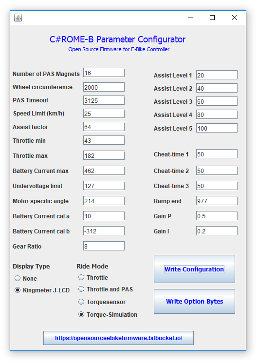
The new parmeters for PI-Control and enhanced speed limiting are implemented in the java-tool now.

fetch.php


Regards
stancecoke
 
stancecoke said:
The new parmeters for PI-Control and enhanced speed limiting are implemented in the java-tool now.
Are you getting feedback from users using the Java tool?

About the torque sensor from BMSBattery, I already installed on my son EBike. The installation is simple but that Q factor / pedal offset on the left side, I don't know if I will like it when riding........

 
Implemented the issue #12: Cruise control: should not start before 6km/h.

Now that the safety features seems implemented, I will move to implement PAS and Torque Sensor.

Stancecoke, what do you think of this algorithm for Torque Sensor:
- PAS cadence will be calculated using the Timer2 ticks between each pin change interrupt
- analog torque pulse:
-- every PWM cycle, read 8bits ADC and save if value is max, to ui8_adc_torque_sensor_max
-- every 100ms on ebike_app.c ebike_app_controller(), save ui8_adc_torque_sensor_max to ui8_adc_torque_sensor and reset the value of ui8_adc_torque_sensor_max. Use ui8_adc_torque_sensor as the value from the torque sensor!
 
casainho said:
Are you getting feedback from users using the Java tool?
Not yet. I got no feedback so far.

casainho said:
Stancecoke, what do you think of this algorithm for Torque Sensor....
If you look at the Torque-Simulation branch, you will see, that I only use the falling edge of the PAS-signal for interrupt, as the dutycycle of the PAS signal is <>0.5
I take an ADC value of the torque at every PAS interrupt and save it in an array that has the same length as the number PAS interrupts (=magnets in the PAS disc) per crank revolution. For the calculation of the current target I sum up all array elements. So it's a mean value of the torque per crank revolution.
There is no need to take adc values of the torque every 64µs...

regards
stancecoke
 
How much magnets does this BMSBattery have on the PAS?
I would like to read the max peak values, they represent the torque, right?
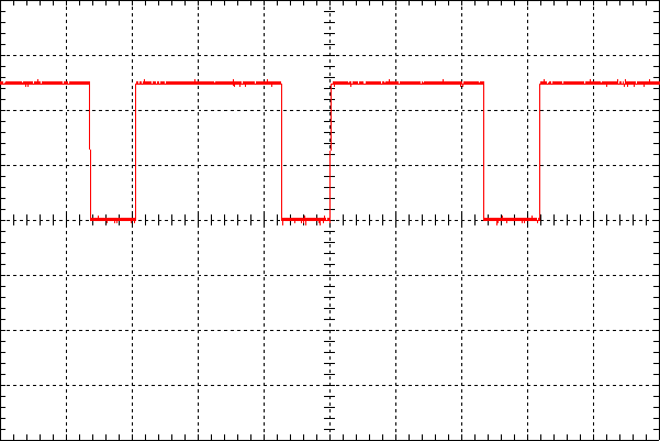
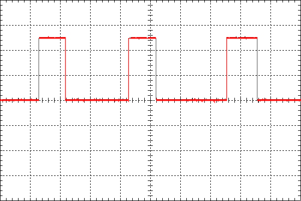
Do you have an image showing the PAS signals and torque sensor signals?
 
casainho said:
How much magnets does this BMSBattery have on the PAS?
There are 12 magnets on the PAS disk:

index.php


casainho said:
I would like to read the max peak values, they represent the torque, right?
The peak ADC values are the peak torque values of course. The torque at the crank is some kind of sinusodial.

casainho said:
Do you have an image showing the PAS signals and torque sensor signals?
For PAS in principle, see the very detailed explanation here.

Turning pedals forewards:

5248.png


Turning pedals backwards:

5249.png


The Signal of the torque is shown here in principle (taken from the sempu-homepage)

20150416112843_4011.jpg


Regards
stancecoke
 
stancecoke said:
There is no need to take adc values of the torque every 64µs...
Yes.
But recently I removed all functions calls inside the PWM interrupt and the processing time now is only 27.2us in 64us, which means we should have like a free 30us :)

Anyway, I want to see the signals of torque sensor and find a way to do it. I would like to read the max/peak values but I understand the mean value should also work.
 
stancecoke said:
casainho said:
How much magnets does this BMSBattery have on the PAS?
There are 12 magnets on the PAS disk:
Thank you for all this technical documentation!! I will now save it on the project page :)

Ok, I was thinking it could have like 5 magnets (or even less) like some PAS and that way, with only 5 points to read the 2 "sinewaves", it could miss the max/peak points. But with 12, it think at least 2 points should be very near the max/peak points.

BUT, seems that reading at signal only when there is a PAS magnet signal change, that means user really need to move the crank before we can detect the force and I would like to be able to read the force even if the crank is blocked like on start pedaling -- do you think this makes sense? does your implementation detects the force before the crank rotates a bit?

I really would like to feel the help of the motor when I make the very first force on the crank, with my foot, without me needing to do the full needed force to move the bicycle.
 
Then you can read the torque in the same way, than you read the throttle. See the code of the forumscontroller, it does it in the same way

Code:
#if CONTROL_MODE == CONTROL_MODE_TORQUE                      //human power control mode
#if defined(SUPPORT_XCELL_RT) || defined(SUPPORT_SEMPU)
    power_poti = poti_stat/102300.0* curr_power_poti_max*power_human*(1+spd/20.0); //power_poti_max is in this control mode interpreted as percentage. Example: power_poti_max=200 means; motor power = 200% of human power
#ifdef SUPPORT_TORQUE_THROTTLE                              //we want to trigger throttle just by pedal torque
    if (abs(torque_instant)>torque_throttle_min)            //we are above the threshold to trigger throttle
    {
      double power_torque_throttle = abs(torque_instant/torque_throttle_full*poti_stat/1023*curr_power_max);  //translate torque_throttle_full to maximum power
      power_throttle = max(power_throttle,power_torque_throttle); //decide if thumb throttle or torque throttle are higher
      power_throttle = constrain(power_throttle,0,curr_power_max); //constrain throttle value to maximum power 
}

But remember this is exactly the situaltion, where the risk to burn your mosfets is the highest.... (I hope the current control loop will always be fast enough ;))

regards
stancecoke
 
stancecoke said:
Then you can read the torque in the same way, than you read the throttle.
Since you are experienced and really want to use torque sensor, can you please tell me if for you, is important or not to instantaneously motor help when start pedaling? Maybe I am missing something.
I have no experience with torque sensor, only with PAS and throttle - and I don't like PAS because I need to turn crank before the motor starts.

stancecoke said:
But remember this is exactly the situaltion, where the risk to burn your mosfets is the highest.... (I hope the current control loop will always be fast enough ;))
Current loop runs every PWM cycle so it is really fast!! I can put throttle immediately to 100% and the current controller works well. And as discussed before, the rise on the current should take a some PWM cycles, so it is slower than we can act.

Next, I am thinking in enable the watch dog timer, maybe put it reseting the system if we don't reset watch dog timer in a 100us window and so we would need to reset every PWM cycle -- this way to make sure code like motor max current and regen max current controllers are working as also PWM duty_cycle ramp up/down controllers.
 
I don't miss the motor power when starting to pedal. But that's just my personal opinion, in the german pedelecforum, there are many people who wanted the behavior as you describe, therefore the code of the "forumscontroller" was modified to have a "torque throttle" for start up.

I've tried to get my BionX direct drive running on my bike with our firmware today, but it failed. I tried all combinations of Hall- and Phasewire connections and tried several values for MOTOR_ROTOR_DELTA_PHASE_ANGLE_RIGHT. The motor runs noisy and draws too much current in the best case :-(

Regards
stancecoke
 
Interesting on the Bionyx. Wonder if it has 60 degree halls instead of 120, or has that been addressed? In my controller the code looks at the hall sequence and trips if they are wrong. So instead of running rough and possibly damaging something, it will keep tripping until the sequence is correct.

On the switch case statement for hall states, I've read (and experienced) that switch case statements are a bit unpredictable as to resources they use, depending on the compiler's decisions. They can use a lot of stack space and a lot of code which can be bad for real time and particularly bad in an interrupt handler.

In my own project I've decided to try the recommended approach of a function pointer table to replace the switch case.
 
stancecoke said:
I've tried to get my BionX direct drive running on my bike with our firmware today, but it failed. I tried all combinations of Hall- and Phasewire connections and tried several values for MOTOR_ROTOR_DELTA_PHASE_ANGLE_RIGHT. The motor runs noisy and draws too much current in the best case :-(
What to do in this case?? Maybe:
1. look at hall sensors signals and see that they are what we expect: 60 degrees between each changes
2. put a small resistor between each 2 phases and measure with the oscilloscope and look at the generated voltage BEMF, which should be sinewave (??) and also compare with the hall sensors signal.

stancecoke said:
I don't miss the motor power when starting to pedal. But that's just my personal opinion, in the german pedelecforum, there are many people who wanted the behavior as you describe, therefore the code of the "forumscontroller" was modified to have a "torque throttle" for start up.
Good to know I am not alone.
I miss because I drive my EBike as I drive my electric car, it only works has 1 gear and heavy :) so need to make a lot of torque with my legs to start pedaling.

And this let me think on another idea!! For instance, the new Leaf electric car version says it can be driven with only 1 pedal, for accelerating, decelerating and even brake/full stop of the car. The same happens with the electric unicycle, where we don't have mechanical brakes.

What about using torque sensor for defining the ebike speed, from increasing the speed up do decrease/brake?? Just like the fixed gear bikes (yes, I like to ride them), that we reduce the crank speed when we want to reduce the bike speed as also to stop. With a direct drive motor, I think we could do this. I never tested an analog brake for command motor regen/brake but I think the torque sensor could be used for that (well, even PAS). Is this idea crazy?
 
Back
Top