KT motor controllers -- Flexible OpenSource firmware for BMSBattery S/Kunteng KT motor controllers (0.25kW up to 5kW)

geofft said:
Spent an hour in the garage earlier with the bike up on a test stand and can now give you some more information on the problems i had with my previous test ride.

1) The bike does not like being pushed in reverse - it's ok for about a metre or so but then the motor resists and at times will actively drive the bike forwards quite forcibly. This could create some dangerous situations and needs some attention.

....this is definitely being caused by reverse pas being mis-interpreted by the firmware. If I reverse pedal fairly quickly all is well, but if I reverse pedal very slowly (as would happen pushing the bike backwards) the motor gives strong drive pulses. A short video here:-https://www.youtube.com/watch?v=2ZvIl2bwB7Y
...so it seems the pas detection needs a little more work..?
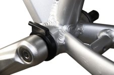
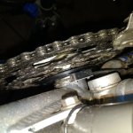
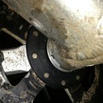
My PAS has 5 magnets and I can't replicate your issue. Can you please take a picture of your PAS? I would like to try understand if the magnets have the same space between them as their size, because:

stancecoke said:
In the "Forumscontroller-" code it is solved by checking the ratio of the PAS_High_counter to the PAS_Low_counter
I am also doing the same:
Code:
#if (PAS_DIRECTION == PAS_DIRECTION_RIGHT)
      if (ui16_pas_on_time_counter > ui16_pas_off_time_counter)
#else
      if (ui16_pas_on_time_counter <= ui16_pas_off_time_counter)
#endif
      { ui8_pas_direction = 1; }
      else { ui8_pas_direction = 0; }

      ui16_pas_off_time_counter = 0;
      ui16_pas_on_time_counter = 0;
    }
  }

Code:
void read_pas_cadence_and_direction (void)
{
  // cadence in RPM =  60 / (ui16_pas_timer2_ticks * PAS_NUMBER_MAGNETS * 0.000064)
  if (ui16_pas_pwm_cycles_ticks >= ((uint16_t) PAS_ABSOLUTE_MIN_CADENCE_PWM_CYCLE_TICKS)) { ui8_pas_cadence_rpm = 0; }
  else
  {
    ui8_pas_cadence_rpm = (uint8_t) (60 / (((float) ui16_pas_pwm_cycles_ticks) * ((float) PAS_NUMBER_MAGNETS) * 0.000064));

    if (ui8_pas_cadence_rpm > ((uint8_t) PAS_MAX_CADENCE_RPM))
    {
      ui8_pas_cadence_rpm = ((uint8_t) PAS_MAX_CADENCE_RPM);
    }
  }

  if (ui8_pas_direction) { ui8_pas_cadence_rpm = 0; }
}
So when ui8_pas_direction = 1, the ui8_pas_cadence_rpm = 0. And that seems to happen when the pedals rotate backwards at medium speed but not at low speed, as seen on the video.....

Here is a log I took just now when testing -- for me, ui8_pas_direction seems to always be = 1 when rotating backwards, even very slow...:
 
Hmm...very strange. I had to change my pas direction in the config from right to left, could that be significant in any way?

Anyway, have attached a couple of photos but I think my pas sensor installation is fairly typical of what's out there...

When I check the display comms keys later I'll play around with the sensor spacing, etc, to see if that helps. However I guess the code will eventually need to work on any pas installation in the same way the stock firmware does now..
 

Attachments

  • PAS sensor(1).jpg
    PAS sensor(1).jpg
    43.1 KB · Views: 1,774
  • PAS sensor(2).jpg
    PAS sensor(2).jpg
    45 KB · Views: 1,774
geofft said:
Hmm...very strange. I had to change my pas direction in the config from right to left, could that be significant in any way?
I also had to change, but still works for me.

geofft said:
Anyway, have attached a couple of photos but I think my pas sensor installation is fairly typical of what's out there...

When I check the display comms keys later I'll play around with the sensor spacing, etc, to see if that helps. However I guess the code will eventually need to work on any pas installation in the same way the stock firmware does now..
Look, the code compares the time of the square wave output signal of PAS. The time on VERSUS time off, and looking at your second picture, is very clear that magnets are far from each other on the disk so the time on VERSUS time off should work well for detecting direction.
Also looking at your first picture, the PAS seems to be well installed, just like mine, with a good distance from the disk with magnets to the sensor.

The difference you have from me, is the 10 magnets while I have 5. That means your PAS signal will change at half of the time for the same cadence.... I can't see a reason for the code to fail... it is not hard the code, it is simple to follow...

Are you ready to be a developer??
Eheh, a bit of a joke but the true is that maybe you can help going deeper so we can understand this issue. As you can see on my real time log graph, the ui8_pas_direction is 1 when rotating backwards and would be important to verify his value when you rotate backwards...
I don't ask you to connect a serial cable and install the log software, but instead to change a line on the firmware and look the LCD:

Find this line:
Code:
if (brake_is_set ()) { ui8_moving_indication |= (1 << 5); }

And change to this:
Code:
if (ui8_pas_direction) { ui8_moving_indication |= (1 << 5); }
So, looking at LCD, would will see brake symbol when ui8_pas_direction = 1, that should happen when rotating the pedals backwards -- please do the same test as before.
 
Find this line:
CODE: SELECT ALL

if (brake_is_set ()) { ui8_moving_indication |= (1 << 5); }
And change to this:
CODE: SELECT ALL

if (ui8_pas_direction) { ui8_moving_indication |= (1 << 5); }
So, looking at LCD, would will see brake symbol when ui8_pas_direction = 1, that should happen when rotating the pedals backwards -- please do the same test as before.

..ok, I think I should be able to do that. In which file this code is located..?

The strange thing is I suddenly remembered that I had exactly this same issue (with reverse pas) when I first tried the Torque Simulation branch a while back - making me think this is something peculiar to my setup - but...it works fine on the stock firmware. Anyway, I should get to do this tomorrow, I'll let you know how it goes.
 
geofft said:
..ok, I think I should be able to do that. In which file this code is located..?
ebike_app.c --> void communications_controller (void)

Code:
  // prepare moving indication info
  ui8_moving_indication = 0;
  if (brake_is_set ()) { ui8_moving_indication |= (1 << 5); }
  if (ebike_app_cruise_control_is_set ()) { ui8_moving_indication |= (1 << 3); }
  if (throttle_is_set ()) { ui8_moving_indication |= (1 << 1); }
//  if (pas_is_set ()) { ui8_moving_indication |= (1 << 4); }
As you can see, there is commented code for PAS activation symbol on LCD, and I don't remember to test that, if bit 4 of ui8_moving_indication will enable the PAS symbol on LCD.

Maybe you can uncomment that line and put:
Code:
  if (ui8_pas_direction) { ui8_moving_indication |= (1 << 4); }
 
casainho said:
stancecoke said:
In the "Forumscontroller-" code it is solved by checking the ratio of the PAS_High_counter to the PAS_Low_counter
I am also doing the same...

You are just looking, if one value is bigger than the other (I know, I suggested to do so, some time ago), not if the ratio is in a certain range.
Code:
ratio = ui16_pas_on_time_counter / ui16_pas_off_time_counter;

regards
stancecoke
 
Ok, I see!! Look to see if like the on pulse is like 2x bigger than off pulse. Maybe that will work better...
Like, cadence is a valid value only if ratio >= 2, other wise, will be zero.

I will rethink to make that code. Don't know if I will be able to make on the weekend, depends on the girlfriend!
 
Guys look at this PAS sensor
http://s.aliexpress.com/3i2MNFjq?fromSns=Copy
Direction detection works also on stock firmware, has 6 magnets usualy but you can buy spare and add to have 12 - precise/fast controll. Easy installing/service, good looking. Working on 10+ bikes I have built with no issues. You can get it at pswpower.com for 3$ when buying controller.

Purpose of posting this is that I think you should make the firmware working the best way for some "recommended" setup and from all pas sensors on the market, this is the one by my opinion :)

Just an idea after reading all this stuff I dont understand :D
 

Attachments

  • 20141110163427_96432.jpg
    20141110163427_96432.jpg
    23.6 KB · Views: 1,750
I went to verify that pas_ratio:
Code:
f_pas_on_off_time_ratio = ((float) ui16_pas_on_time_counter) / ((float) ui16_pas_off_time_counter);
really works as stancecoke pointed out.

On this screenshot, we can see on the first part I was pedaling forward and after backward (still, at inversion and very low cadence, result may be wrong so a minimum cadence value must be imposed):


One question to geofft: the cadence on your video is kind of slow, maybe we can just increase the minimum cadence after which it is considered a good value?? The thing is: the original firmware don't seem to have an option to adjust PAS_ratio min and max value, as the guys does with that Arduino... that would be another 2 values for the user to configure on the firmware.... :-(

Here is the code on firmware:
Code:
  // limit min PAS cadence
  if (ui16_pas_counter > ((uint16_t) PAS_ABSOLUTE_MIN_CADENCE_PWM_CYCLE_TICKS))
  {
    ui16_pas_pwm_cycles_ticks = (uint16_t) PAS_ABSOLUTE_MIN_CADENCE_PWM_CYCLE_TICKS;
    ui16_pas_counter = 0;
    ui16_pas_on_time_counter = 0;
    ui16_pas_off_time_counter = 0;
    ui8_pas_direction = 1;
  }

You can adjust on main.h:
Code:
#define PAS_ABSOLUTE_MIN_CADENCE_PWM_CYCLE_TICKS  (156250 / PAS_NUMBER_MAGNETS) // min hard limit to 6RPM PAS cadence
You will need to lower the value of 156250, that as you can see is for 6 RPM. Can it work ok with minimum 10 RPM? 15 RPM?
 
Ok, that sounds like it's definitely worth a try, the problem doesn't seem to happen if I increase the reverse cadence a little.

I'm slightly confused by the arithmetic in that line of code, what would I need to reduce the 156250 number down to, to get to maybe, 15rpm?
 
geofft said:
I'm slightly confused by the arithmetic in that line of code, what would I need to reduce the 156250 number down to, to get to maybe, 15rpm?
Let's learn: the code increments ui16_pas_counter every PWM cycle, between every positive pulse of PAS signal. The higher higher the cadence, the smaller is the time between pulses and so is lower the ui16_pas_counter value, that is compared with
PAS_ABSOLUTE_MIN_CADENCE_PWM_CYCLE_TICKS (the code I posted before).
 
geofft said:
I'm slightly confused by the arithmetic in that line of code, what would I need to reduce the 156250 number down to, to get to maybe, 15rpm?
Just now I did understand your question. To have 12 RPM, just use half of that value and so on.
 
Just now I did understand your question. To have 12 RPM, just use half of that value and so on.

Ah! That's what I was asking, thanks. You have to remember that you're talking to an idiot here.... :wink:

Hoping to get out to the garage later this morning, will give this a try.
 
casainho said:
The thing is: the original firmware don't seem to have an option to adjust PAS_ratio min and max value

With the Parameter C1 in the Display, you can choose from 8 different PAS settings. We just don't know what is done with this value internally in the original firmware...

regards
stancecoke

PAS.PNG
 
I was looking again to that yesterday. My interpretation:
- that parmeter value can be only: 0, 1, 2 , 5, 6, 7
- values 0, 1, 2 will consider pedals rotating left while others rotating right, for a correct output value of cadence (differentiate between pedalling forwards versus backwards)
- that 5, 8 and 10 signal shoild refer to the number of magnets on the PAS disk
- the sart sensitivity may be (3 possible fixed values) the minimum cadence value or minimum output value of the algorithm (I bet on the first one)
 
yes, this sounds reasonable.

completly other topic: Do you think it is possible to set the PWM frequency to something about 21kHz? In the german forum we are just discussing to control a Yamaha Mid-Drive with the S06S. With 520 eprs we get just 86 rpm maximum for the chainwheel, that's too slow. It should be at least 120 rpm.
Will it work with just 48µs cycle time in PWM? Or will we get a stack overflow?

regards
stancecoke
 
I did run at begin at 20khz, I think you should found on git logs.

We just need to make sure the code running on the PWM cycle takes less time and leave some free time for the slow loop code processing.
Also, I don't know what are the implications on hardware. At least it will be more commutations and so more heat generated on the power mosfets.
 
Sorry guys, but just spent a frustrating couple of hours in the garage getting absolutely nowhere.

Thought I'd make a clean start and downloaded the most recent firmware from github and now seem to have run into all sorts of new path/file associations issues. Probably simple problems for you guys but for me just more frustration.

Before I go any further can I ask just one simple question - when you unzip the firmware (BMSbattery_S_controllers....etc) does it need to go to a specific location in C drive for things to work properly or is it ok in C:\(root)....?
 
I am sorry. I think the issue is because I changed the firmware to be inside of firmware folder while before was on root/base folder.

I suggest you to just edit the config.h (and main.h) and call the scripts to build.
Maybe the scripts hide from you the result of build the firmware... Because ideally you would look at the result of build and you would understand if build went ok. Then, it is just the command to flash the firmware on the S06S, that you need to do on your garage.

I think Stancecoke is the one that can help you.
I have now a computer with Windows that I want to start testing all the process...

And I think you need to call the scripts while you are at the same folder that they are, you need to navigate to their folder while on the command line.
 
Ok, I understand.
Will try again, maybe tomorrow.
 
geofft said:
Before I go any further can I ask just one simple question - when you unzip the firmware (BMSbattery_S_controllers....etc) does it need to go to a specific location in C drive for things to work properly or is it ok in C:\(root)....?
You don't have to choose a certain location. Directly in root is OK.

Which way to start the flashing process did you choose?
- double click on "firmware_configuration_tool.jar"
- double click on "OSEC Parameter Configurator.jar"
- double click on "Start_compiling.bat" in firmware folder
- double click on "Start_compiling.bat" in configuration_tool/windows_scripts/ folder

Did you get any error message?

regards
stancecoke
 
I attempted 3 of those 4 methods, all had some problem. Can't remember details just now, but have some notes out in garage I made at the time.

Will recheck all methods and give further details, hopefully tomorrow. The Merlot is tasting too good to bother tonight.... :wink:
 
stancecoke said:
geofft said:
Before I go any further can I ask just one simple question - when you unzip the firmware (BMSbattery_S_controllers....etc) does it need to go to a specific location in C drive for things to work properly or is it ok in C:\(root)....?
You don't have to choose a certain location. Directly in root is OK.

Which way to start the flashing process did you choose?
- double click on "firmware_configuration_tool.jar"
- double click on "OSEC Parameter Configurator.jar"
- double click on "Start_compiling.bat" in firmware folder
- double click on "Start_compiling.bat" in configuration_tool/windows_scripts/ folder

Did you get any error message?

I've just retrieved my notes from the garage and I'll give quick feedback for your question now. I'm only 90% sure that the information is accurate and will retry all options later today and correct if necessary. You may be best advised to wait until I've done that. I'll label the 4 flashing options thus:-

A)- double click on "firmware_configuration_tool.jar"
B)- double click on "OSEC Parameter Configurator.jar"
C)- double click on "Start_compiling.bat" in firmware folder
D)- double click on "Start_compiling.bat" in configuration_tool/windows_scripts/ folder


A) Did seem to work immediately after unzip/installing but after trying B and C something became corrupted and flashing failed with 'can't find main.ihx' error in cmd log.

B) Doesn't compile and triggers a windows message saying 'can't find windows_scripts\startcompiling'

C) Compiles but fails to flash data with can't find main.hex error in cmd log.

D) Didn't try this option, will do so later today.

Another confusing factor is that after running these options config.h files appear in both the root and firmware folders and you have to work out which one to modify if running 'start_compiling.bat' directly.
 
@geofft: OK, so that is really confusing. I have to check it.
You don't have to try the fourth option, it won't work.

I suggest to work with option A on a fresh unzipped base.

@casainho: Where do I set the PWM frequency)
I guess it is this part:
Code:
TIM1_TimeBaseInit(0, // TIM1_Prescaler = 0
		    TIM1_COUNTERMODE_CENTERALIGNED1,
		    (512 - 1), // clock = 16MHz; counter period = 1024; PWM freq = 16MHz / 1024 = 15.625kHz;
		    //(BUT PWM center aligned mode needs twice the frequency)
1); // will fire the TIM1_IT_UPDATE at every PWM period

With this we should get a PWM frequency of 20.833 kHz (16Mhz / (2*384) = 20.833kHz)
Code:
TIM1_TimeBaseInit(0, // TIM1_Prescaler = 0
		    TIM1_COUNTERMODE_CENTERALIGNED1,
		    (384 - 1), // clock = 16MHz; counter period = 384; PWM freq = 16MHz / (384*2) = 20.833kHz;
		    //(BUT PWM center aligned mode needs twice the frequency)
1); // will fire the TIM1_IT_UPDATE at every PWM period

regards
stancecoke
 
We should decide, if we want to keep both java tools. I set the pathes in the OSEC Parameter Configurator.jar so it can be run directly from the firmware folder again.

So options A, B and C should work now!

geofft said:
A) ... flashing failed with 'can't find main.ihx' error in cmd log.

C) Compiles but fails to flash data with can't find main.hex error in cmd log.

after reading this again, I guess, that you get an error while compiling, as the main.hex / main.ihx can't be found. Can you check the log again?

regards
stancecoke
 
Back
Top