Lebowski's motor controller IC, schematic & setup, new v2.A1

Reveiced the chip today, many thanks @L.
Now I printed the manual and tomorrow I will order two or three mitsubhisi fm600tu-3a mosfet moduls :D

what input capacity do I need for 60V and 200amps and 120V and 450amps? 8)
 
c_a said:
Reveiced the chip today, many thanks @L.
Now I printed the manual and tomorrow I will order two or three mitsubhisi fm600tu-3a mosfet moduls :D

what input capacity do I need for 60V and 200amps and 120V and 450amps? 8)
These moduals mention drain current rms 300a and peak pulsed drain at 600a so would that meen you can pulse them to =or< 600 amps during pwm...?
They do look nice 110mm x 90mm is a nice size but they are slow switching... They have low rdson for a 150v product. Hmmmm I am interested to see what real world numbers we can get from them.
 
whatever said:
question from a novice:
xie cheng controller ( infineon chip or newer one) you cant read what values are already set in the controller ( phase amps etc etc)( unless someone has worked it out) will it be possible to read what values are already set in this chip?

yes there's no data protection... which also means you can totally mess it up :shock:
 
what I mean is, if you set certain parameters ( say phase amps for example), is it possible to read from the controller ( via computer)
what value you've set previously?
 
whatever said:
what I mean is, if you set certain parameters ( say phase amps for example), is it possible to read from the controller ( via computer)
what value you've set previously?

In the setup menu it gives the value that is currently set so you can see which value
is being used right now. It does not remember the 'history' or past settings of a value.
 
does the controller have a e-brake function, like you see on many of the chinese controllers?

this way you wont be able to brake and power the bike at the same time, a nice safety feature if your throttle gets stuck WOT for some reason.

(this could be done with the reset switch, but i don't know if the controller likes it to be reset all the time?)
 
nieles said:
does the controller have a e-brake function, like you see on many of the chinese controllers?

this way you wont be able to brake and power the bike at the same time, a nice safety feature if your throttle gets stuck WOT for some reason.

(this could be done with the reset switch, but i don't know if the controller likes it to be reset all the time?)

I don't know what an e-brake function is, but if you need some sort of safety switch to bypass the
throttle... You can give a reset as you suggest, this will turn off all the FET's and let the motor
spin freely until e-rpm has dropped until almost standstill. Another option is to connect a switch
between the throttle input (pin 9 or 10) and ground. The 1000 ohm resistor between the throttle
(hall or potentiometer) will limit the current, you can increase this resistor to 2200 if you want to
limit the current even further.
The difference between the two methods is that issuing a reset will put the controller back in
drive 0, something which it will only transition out of when the motor is close to standstill.
Shortening the throttle to ground is the same as closing throttle, when you remove the short
you regain immediate throttle response.

How is it going with your controller build ?
 
Lebowski said:
I don't know what an e-brake function is, but if you need some sort of safety switch to bypass the
throttle... You can give a reset as you suggest, this will turn off all the FET's and let the motor
spin freely until e-rpm has dropped until almost standstill. Another option is to connect a switch
between the throttle input (pin 9 or 10) and ground. The 1000 ohm resistor between the throttle
(hall or potentiometer) will limit the current, you can increase this resistor to 2200 if you want to
limit the current even further.
The difference between the two methods is that issuing a reset will put the controller back in
drive 0, something which it will only transition out of when the motor is close to standstill.
Shortening the throttle to ground is the same as closing throttle, when you remove the short
you regain immediate throttle response.

How is it going with your controller build ?

the e-brake is basicly what you discribed, it cuts the throttle when you apply the brake (there are brakes with build-in reed switches)

what would be awsome, is to have a switch like the reset, but with the folowing function:
when connected to gnd or floating, turn all fets off
when connected to 5v again it will return to the previous drive (0,1,2 or 3)
before enabling the throttle, wait for the throttle to be zero.(but not for the motor to be near zero rpm)

(pin 22 could be used for this?)

about my controller build;
i made some small pcb's for my current sensors this weekend, so i should be able to get the controller working on the breadboard sometime this week.
 
Do I understand correctly that this will allow smooth regen rather than on/off style of infineon controllers? If that's the case I'm sure many of us on the forum would love to purchase a fully made controller for our typical hub motors that has that feature. If it was combined with a ready-made analog brake lever they would sell like hotcakes imo.
 
LegendLength said:
Do I understand correctly that this will allow smooth regen rather than on/off style of infineon controllers? If that's the case I'm sure many of us on the forum would love to purchase a fully made controller for our typical hub motors that has that feature. If it was combined with a ready-made analog brake lever they would sell like hotcakes imo.
You have to understand this is going to be for a $1000-2000 type controller right? This might be something we can get to happen as a kit but even then it will not be cheep!
 
I just recived the two chips you sent me and gordo. Thanks Lebowski! I am excited to get all this working!
 
LegendLength said:
Do I understand correctly that this will allow smooth regen rather than on/off style of infineon controllers? If that's the case I'm sure many of us on the forum would love to purchase a fully made controller for our typical hub motors that has that feature. If it was combined with a ready-made analog brake lever they would sell like hotcakes imo.

In Kelly-speak: it has variable-strength regen :D

I haven't really thought about making controllers or kits yet, first I want to see how it works with other motors,
this is why I emailed some chips around to interested people...
 
LegendLength said:
Arlo1 said:
You have to understand this is going to be for a $1000-2000 type controller right?

Ahh sorry I didn't realize that.
Sorry guys I was proly wrong to word that, that way. But I don't know how you would get all the features lebowski wrote to work with out spending some money and a lot of time to get it all set up. The best thing for someone on a budget is get a chip from lebloski and do the rest him self. Over the next few weeks I will get onto this and see how it goes then keep rough track of my time so I can help with a cost analyst.
 
thanks lebowski for that, its a step up on the xiecheng controllers, you actually will know what your settings are!
I think xiecheng would be interested in this
 
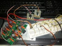
A sneakpeak of my controller build.

still on a breadboard, i will etch a pcb for the controller chip as soon as i have the controller running.

IMG_20120225_181027 (1).jpg
 
Lebowski said:
I don't see them in the picture, please don't forget the series resistors in the wires coming
from the motor terminals to the 6 diodes !

they are there.. they are in the middle part of the wire that is not in the picture.

also not shown in the picture is the connector cable for the outputs, i just soldered up a wire harnass for this.

with a bit of luck tomorrow i can post a little movie spinning up a motor.
 
my progress for today.

connected the output stage to the controller and tested the PWM signals with a scope and looked good.

next i tried to spin my motor, but it didnt spin. not sure what i am doing wrong

when the motor is not spinning and i do not apply any throttle the controller is in drive 2.
there is a 50% duty cycle signal on the ouput stage(measured at the gate of high side fet C, see picture)

these are the latest settings in the controller:

Code:
########################################
#   (c)opyright 2012, B.M. Putter      #
#   Adliswil, Switzerland              #
#   bmp72@hotmail.com                  #
#                                      #
#  experimental, use at your own risk  #
########################################


a] calibrate hall sensors
b] determine coil positions
c) PWM parameters
d) current settings
e) control loop parameters
f) throttle setup
g) running modes
h) CAN bus setup
z) store parameters in EEPROM for motor use

------> c 

a) PWM frequency: 20kHz
b) deadtime: 599ns
c) dutycycle testsignal: 50%
d) toggle high side polarity, now active HIGH
e) toggle low side polarity, now active HIGH
f) test PWM signals
z) return to main menu

------> z 

########################################
#   (c)opyright 2012, B.M. Putter      #
#   Adliswil, Switzerland              #
#   bmp72@hotmail.com                  #
#                                      #
#  experimental, use at your own risk  #
########################################


a] calibrate hall sensors
b] determine coil positions
c) PWM parameters
d) current settings
e) control loop parameters
f) throttle setup
g) running modes
h) CAN bus setup
z) store parameters in EEPROM for motor use

------> d 

a) number of current sensors: 2
b) current sensor transimpedance: 10.00 mV/A
c) maximum motor phase current: 19.9 A
d) maximum battery current, motor use: 4.9 A
e) maximum battery current, regen: 0.0 A
f) maximum shutdown error current, fixed: 1.9 A
g) maximum shutdown error current, proportional: 1.9 A
h) IIR filter coefficient: 5
i) use additional comb filter: YES
z) return to main menu

------> z 

########################################
#   (c)opyright 2012, B.M. Putter      #
#   Adliswil, Switzerland              #
#   bmp72@hotmail.com                  #
#                                      #
#  experimental, use at your own risk  #
########################################


a] calibrate hall sensors
b] determine coil positions
c) PWM parameters
d) current settings
e) control loop parameters
f) throttle setup
g) running modes
h) CAN bus setup
z) store parameters in EEPROM for motor use

------> e 

a) loop sample frequency: 38.01 kHz
b) 1st order phase loop integrator coefficient: 12.7999
c) 2nd order phase loop integrator coefficient: 0.0709
d) amplitude loop integrator coefficient: 3.0000
e) maximum amplitude: 200 %
z) return to main menu

------> z 

########################################
#   (c)opyright 2012, B.M. Putter      #
#   Adliswil, Switzerland              #
#   bmp72@hotmail.com                  #
#                                      #
#  experimental, use at your own risk  #
########################################


a] calibrate hall sensors
b] determine coil positions
c) PWM parameters
d) current settings
e) control loop parameters
f) throttle setup
g) running modes
h) CAN bus setup
z) store parameters in EEPROM for motor use

------> f 
a) calibrate throttle 1
b) calibrate throttle 2
c) polynomal coefficients throttle 1 (x, x^2, x^3): 1.0000, 0.0000, 0.0000
d) polynomal coefficients throttle 2 (x, x^2, x^3): -0.0002, -0.0002, -0.0002
e) use analog throttle 1: YES
f) use analog throttle 2: NO
   receive throttle over CAN: NO
g) TX throttle over CAN: NO
h) test throttle
z) return to main menu

------> z 

########################################
#   (c)opyright 2012, B.M. Putter      #
#   Adliswil, Switzerland              #
#   bmp72@hotmail.com                  #
#                                      #
#  experimental, use at your own risk  #
########################################


a] calibrate hall sensors
b] determine coil positions
c) PWM parameters
d) current settings
e) control loop parameters
f) throttle setup
g) running modes
h) CAN bus setup
z) store parameters in EEPROM for motor use

------> g 
a) sensored or sensorless: SENSORLESS
b} sensorless startup: SELF START
c} e-rpm limit sensorless self start: 382
d} e-rpm reached before transition: 81 %
e} minimum current push start: 4.9 A
f} push start current, error allowed: 25 %
g] erpm sensored to sensorless transition: 500
h] transition time sensored to sensorless: 99 milli-sec 
i) return to motor start below 107 erpm
j) controlled slowdown for direction change: YES
k) phase current for controlled slowdown: 0.9 A 
l) motor maximum, forward: 39.99 k-erpm 
m) motor maximum, reverse: 3.96 k-erpm 
n) motor standstill voltage threshold: 0.49 V
z) return to main menu

------> z 

########################################
#   (c)opyright 2012, B.M. Putter      #
#   Adliswil, Switzerland              #
#   bmp72@hotmail.com                  #
#                                      #
#  experimental, use at your own risk  #
########################################


a] calibrate hall sensors
b] determine coil positions
c) PWM parameters
d) current settings
e) control loop parameters
f) throttle setup
g) running modes
h) CAN bus setup
z) store parameters in EEPROM for motor use

------> h 
a) CAN 'address': 1990
b) CAN CFG1 as per Microchip 30F manual: 64
c) CAN CFG2 as per Microchip 30F manual: 664
   RS232 output rate: 3802 Hz
z) return to main menu

------> z 

########################################
#   (c)opyright 2012, B.M. Putter      #
#   Adliswil, Switzerland              #
#   bmp72@hotmail.com                  #
#                                      #
#  experimental, use at your own risk  #
########################################


a] calibrate hall sensors
b] determine coil positions
c) PWM parameters
d) current settings
e) control loop parameters
f) throttle setup
g) running modes
h) CAN bus setup
z) store parameters in EEPROM for motor use

------>

 
The 50% dutycycle is OK, it's the midpoint for all 3 motor phases.

Are you using an RC motor ? I would try it with 'push start' first.
Close throttle to get out of drive_0 into drive_1. Then give it some throttle and start it
by hand. Make sure you're spinning it in the correct direction.

some comments about the setup: for and RC motor the 12.8 and 0.071 are a bit low, I would multiply
those by 4 (the values are calculated with y=256, for RC 1024 is better, 1024 is what I used
for spinning my 5-wind small RC motor). I would also up the self-start rpm,
try 800 or 1200 (basically, experiment :D )

I saw you have only 2 current sensors... The first start will be a little
bit more difficult (may require more throttle) as it only calibrates for
current sensor offset in drive_3 (so once it;s been in drive_3 for a few second
the current sensors are calibrated and starting will be more smooth).

Also for self-start, it won't start with no throttle. Did you calibrate
and try out the throttle ?

Remember, its a current based throttle so you need to give enough
throttle to overcome the no-load current spec of your motor !
 
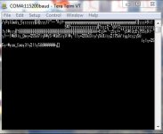
Ok so Im setting this up and this is what Termite spits out.
Code:
00 00 00 00                                      ....            
43                                               C               
00 00 00 00                                      ....            
43                                               C               
bd bd bd bd bd bd bd bd bd bd bd bd bd bd bd bd  ½½½½½½½½½½½½½½½½
bd bd bd bd bd bd bd bd bd bd bd bd bd bd bd cb  ½½½½½½½½½½½½½½½Ë
cb cb cb cb cb cb cb cb cb cb cb cb cb cb cb cb  ËËËËËËËËËËËËËËËË
cb cb cb cb cb cb 5b b9 bf bf bf af 39 ad 21 1f  ËËËËËË[¹¿¿¿¯9­!.
0d 1b 2d 31 2f 17 bf 9b 9f 9d 9b a7 bf 7b a3 65  ..-1/.¿›Ÿ›§¿{£e
a3 bf 5f 15 17 17 35 1b bf bf bf bf bf bf b9 eb  £¿_...5.¿¿¿¿¿¿¹ë
b9 bf bf bf 7d 37 27 2d 19 11 2d 27 a7 bf 59 11  ¹¿¿¿}7'-..-'§¿Y.
2d 17 0b 35 1b 27 3d 23 37 bf bf bf bf bf bf bf  -..5.'=#7¿¿¿¿¿¿¿
bf bf bf bf bf bf bf b9 eb b9 bf bf bf 3b 25 1f  ¿¿¿¿¿¿¿¹ë¹¿¿¿;%.
91 9b 7f 2f 21 17 25 3d 2d 27 a3 39 21 25 bf bf  ‘›/!.%=-'£9!%¿¿
bf bf bf bf bf bf bf bf bf bf bf bf bf bf bf bf  ¿¿¿¿¿¿¿¿¿¿¿¿¿¿¿¿
b9 eb b9 bf bf bf bf bf bf bf bf bf bf bf bf bf  ¹ë¹¿¿¿¿¿¿¿¿¿¿¿¿¿
bf bf bf bf bf bf bf bf bf bf bf bf bf bf bf bf  ¿¿¿¿¿¿¿¿¿¿¿¿¿¿¿¿
bf bf bf bf bf bf bf bf bf b9 eb b9 bf bf 35 0f  ¿¿¿¿¿¿¿¿¿¹ë¹¿¿5.
1f 35 1b 2d 25 35 23 17 3d 27 a7 bf 15 19 35 bf  .5.-%5#.='§¿..5¿
3d 17 bf 0d 21 15 1b bf 21 11 23 bf 1b 2d 19 29  =.¿.!..¿!.#¿.-.)
bf bf b9 eb b9 b9 b9 b9 b9 b9 b9 b9 b9 b9 b9 b9  ¿¿¹ë¹¹¹¹¹¹¹¹¹¹¹¹
b9 b9 b9 b9 b9 b9 b9 b9 b9 b9 b9 b9 b9 b9 b9 b9  ¹¹¹¹¹¹¹¹¹¹¹¹¹¹¹¹
b9 b9 b9 b9 b9 b9 b9 b9 b9 b9 b9 b9 eb eb eb 3d  ¹¹¹¹¹¹¹¹¹¹¹¹ëëë=
45 bf 39 3d 27 2d 3b 1b 3d 17 35 bf 2f 3d 27 27  E¿9='-;.=.5¿/=''
bf 19 35 23 19 21 1b 19 eb 3b 45 bf 37 35 17 35  ¿.5#.!..ë;E¿75.5
1b 25 2d 23 35 bf 39 21 2d 27 bf 1f 21 19 2d 17  .%-#5¿9!-'¿.!.-.
2d 21 23 19 eb 39 ad bf 5f 51 65 bf 1f 3d 1b 3d  -!#.ë9­¿_Qe¿.=.=
25 35 17 35 1b 19 eb 37 ad bf 39 15 1b 1b 35 23  %5.5..ë7­¿9...5#
17 bf 19 35 17 17 2d 23 31 19 eb 35 ad bf 39 21  .¿.5..-#1.ë5­¿9!
23 17 1b 21 27 bf 27 21 21 1f bf 1f 3d 1b 3d 25  #..!'¿'!!.¿.=.=%
35 17 35 1b 19 eb 33 ad bf 17 2f 1b 21 17 17 27  5.5..ë3­¿./.!..'
35 bf 19 35 17 15 1f eb 31 ad bf 1b 15 23 23 2d  5¿.5...ë1­¿..##-
23 31 bf 25 21 37 35 19 eb 2f ad bf 79 7d 63 bf  #1¿%!75.ë/­¿y}c¿
3b 15 19 bf 19 35 17 15 1f eb 0b ad bf 19 17 21  ;..¿.5...ë.­¿..!
1b 35 bf 1f 3d 1b 3d 25 35 17 35 1b 19 bf 2d 23  .5¿.=.=%5.5..¿-#
bf 75 75 5f 5b 61 65 bf 33 21 1b bf 25 21 17 21  ¿uu_[ae¿3!.¿%!.!
1b bf 15 19 35 eb eb a5 a5 a5 a5 a5 a5 83 bf 00  .¿..5ë륥¥¥¥¥ƒ¿.
 
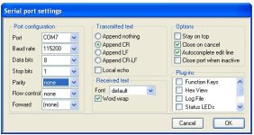
What kind of RS232 cable are you using Arlo ? Nieles found out that for his specific
cable (based on a FT232 chip) he did not need the inversions... further, make
sure the baudrate is set to 115200, 8 bits, 1 stopbit, no parity
termite.JPG
 
This is with teraterm as well. The language it spits out seems wrong. I am using the usb/serial adapter that we use for flashing the xchan china controllers.
 

Attachments

  • Capture leb.JPG
    Capture leb.JPG
    28.1 KB · Views: 3,523
Back
Top