You are using an out of date browser. It may not display this or other websites correctly.
You should upgrade or use an alternative browser.
You should upgrade or use an alternative browser.
Lebowski's motor controller IC, schematic & setup, new v2.A1
- Thread starter Lebowski
- Start date
That last one has a nasty turn offVolttan said:Tomdb said:Any pictures?
Got the the pwm signal working and confirmed with the test signal?
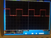
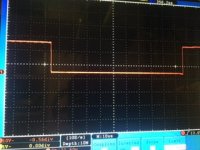
PWM at the terminals of the power stage looks good
a) PWM frequency: 5kHz
b) deadtime: 1700ns
c) dutycycle testsignal: 50%
View attachment 3
View attachment 2
View attachment 1
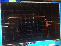
c) dutycycle testsignal: 95%
Tomdb
10 W
What kind of voltage do you see on the output of the powerstage? On each of the phases, and are the current sensors matched to the correct phase?
What are the other settings?
What are the other settings?
Lebowski
10 MW
doesn't look like 95% either..Arlo1 said:That last one has a nasty turn offVolttan said:Tomdb said:Any pictures?
Got the the pwm signal working and confirmed with the test signal?
PWM at the terminals of the power stage looks good
a) PWM frequency: 5kHz
b) deadtime: 1700ns
c) dutycycle testsignal: 50%
View attachment 3
View attachment 2
View attachment 1
c) dutycycle testsignal: 95%
Volttan
1 mW
Lebowski said:doesn't look like 95% either..
Right, I plugged vice versa H and L.
Now I almost works.
Tomdb
You can tell me what the value set?
a) current sensor transimpedance: 6.00 mV/A
and
b) maximum motor phase current: 19.9 A
c) maximum battery current, motor use: 19.9 A
up to the controller powerstage
Tomdb
10 W
Yes the current scaling is around 5.8-6mv/A
The current is up to you.
Got my two new V2.9 chips in, will fit it tomorrow.
The current is up to you.
Got my two new V2.9 chips in, will fit it tomorrow.
kiwifiat
100 W
Arlo1 said:Thankskiwifiat said:You are doing great work with your controller it is really impressive to see what Arlo and others have built with your controller chip.You come to the island ever? You should come ride in the CrX

Thanks, I do from time to time and I will definitely take you up on that next time I am over.
Lebowski said:kiwifiat said:Well no, yes 4 bits but not per e-revolution. Check out the AS5040 from Austria Micro Systems that is good up to 30,000 rpm.
http://www.ams.com/eng/content/download/1285/7214
512 pulses per mechanical revolution for each channel A and B gives 2048 distinct edge transitions per mechanical revolution or 0.175 degrees mechanical. Obviously multiply this by pole pairs to get e-revolution precision but either way significantly better than available from halls. Some available devices have 4096 pulse per channel per mechanical revolution giving even higher precision. Of course the whole point of going sensorless is to avoid the cost of any kind of encoder but the cost of the AS5040 isn't too bad in my opinion.
You are doing great work with your controller it is really impressive to see what Arlo and others have built with your controller chip.
Interfacing and using a chip like this is no big deal... but there are dozens of chips like this on the market and unless there is a universal way of connecting and readout making an interface to the controller IC is no use. Also, who uses this ? Finally, this particular chip can be configured to give hall sensor like output signals, so can be used with the controller IC.
My point was that a quadrature encoder gives significantly better rotor position information than hall effect sensors and while you can interpolate between hall sensor state changes to provide intermediate rotor angle data for your FOC calculations that approach will not be as accurate as using an encoder count as an index to a look up table at slow rotational speeds.There is a universal interface which is the standard A, B channels and an index and the microchip processor you use has an encoder interface as standard.
I assume your chip employs some kind of back emf observer to determine rotor angle and the fact that your controller IC performs so well in the real world proves that there is no need for encoders anymore so purely an academic discussion not "how to suck eggs" thing.
It is great to see a few people over on diyelectriccar using your controller IC with success so keep up the awesome work.
Lebowski
10 MW
Still, the whole purpose of the encoder (at least with the controller IC) is to deliver torque from standstill, also at power up.
I now understand how this encoder works, a motor revolution is divided into many hundreds or thousands of pulses on the A and B lines,
with an occasional synchronisation pulse for absolute position info... and herein lies the problem. When you power up you do not immediately
get absolute position info. A and B will tell you whether the motor moves forward or backward (relative info), but only after you receive the
synchronisation pulse do you have absolute information. So after powering up there is no absolute info, meaning you cannot drive away with
your vehicle. Hall sensors or sine/cosine sensors do give absolute info from power up, giving the critical advantage that you can drive
away with full torque...
kiwifiat
100 W
Lebowski said:Still, the whole purpose of the encoder (at least with the controller IC) is to deliver torque from standstill, also at power up.
I now understand how this encoder works, a motor revolution is divided into many hundreds or thousands of pulses on the A and B lines,
with an occasional synchronisation pulse for absolute position info... and herein lies the problem. When you power up you do not immediately
get absolute position info. A and B will tell you whether the motor moves forward or backward (relative info), but only after you receive the
synchronisation pulse do you have absolute information. So after powering up there is no absolute info, meaning you cannot drive away with
your vehicle. Hall sensors or sine/cosine sensors do give absolute info from power up, giving the critical advantage that you can drive
away with full torque...
That is a very good point. Having to align with the index before driving away is a clunky solution. Given that Microchip, STMicro, and Texas Instruments motor control solutions all include AB encoder support I wonder aside from the obvious "step the motor around until the index is found" if there is a simple solution to this problem.
heathyoung
100 kW
izeman
1 GW
nothing that can't be built with a dremel and a small fileheathyoung said:Price is another question though...
the problem i see with these external methods is, that it can be impossible to mount them due to limited space.
Tomdb
10 W
Got my 220v pack setup. Swapped out the 2.75 for the 2.90 IC plus I added a large cap right after the dc-dc.
On the remy motor it works okay. However the lexus motor I cannot get working or even responding to the throttle.
Hex dump from the lexus setup, keeps showing the overflow in FOC calc menu. I believe that my motor are still not being measured properly for some reason.
On the remy motor it works okay. However the lexus motor I cannot get working or even responding to the throttle.
Hex dump from the lexus setup, keeps showing the overflow in FOC calc menu. I believe that my motor are still not being measured properly for some reason.
Code:
0xFFFF	0xFFFF	0x795E	0x0400	0xFFFF	0xFFFF	0xFFFF	0x000A
0x0000	0x07AE	0x0018	0x0000	0x01E0	0xFFFF	0xF852	0xFFE8
0x0000	0xFE20	0x0000	0x4CCD	0x0018	0x0000	0x01E0	0xFFFF
0xB333	0xFFE8	0x0000	0xFE20	0xFAB5	0xFF06	0xFFFF	0xFFFF
0x36C2	0xFFFF	0xFFFF	0xFFFF	0xFFFF	0xFFFF	0xFFFF	0xFFFF
0xFFFF	0xFFFF	0xFFFF	0xFFFF	0x0017	0x7384	0x040E	0x0103
0x003F	0x00FD	0x0687	0x001A	0x0019	0x0005	0x00C2	0x0151
0xFFFF	0x7FBC	0x0000	0x0164	0x00B2	0x03F7	0x03F4	0x03F5
0x0BB7	0x0358	0x008F	0x0592	0x0006	0x2CF9	0xFFFF	0x0DC0
0x1000	0x0000	0x0000	0xF000	0x0000	0x0000	0x00B1	0x02AF
0x0000	0x03FF	0x0590	0x0047	0x0590	0x0356	0x047C	0x0258
0x0064	0xFFFF	0xFFFF	0xFFFF	0xFFFF	0x0003	0x0000	0x0078
0x0000	0x0000	0xFFFD	0x0000	0xFF88	0x0000	0x0000	0x0005
0x0000	0x0064	0xFFFB	0x0000	0xFF9C	0x000C	0x0000	0x00F0
0xFFF4	0x0000	0xFF10	0x05CC	0xFFFF	0xFFFF	0x026F	0x02C8
0x004E	0x014E	0x026F	0x000F	0x0010	0x0E10	0x0000	0x03E8
0x03B6	0x6000	0x01AB	0x009B	0x4000	0xFFFF	0xFFFF	0xFFFF
0xFFFF	0xFFFF	0xFFFF	0xFFFF	0xFFFF	0xFFFF	0xFFFF	0xFFFF
0xFFFF	0xFFFF	0xFFFF	0xFFFF	0xFFFF	0xFFFF	0xFFFF	0xFFFF
0xFFFF	0xFFFF	0xFFFF	0xFFFF	0xFFFF	0xFFFF	0xFFFF	0xFFFF
0xFFFF	0xFFFF	0xFFFF	0xFFFF	0xFFFF	0xFFFF	0xFFFF	0xFFFF
0xFFFF	0xFFFF	0xFFFF	0xFFFF	0xFFFF	0xFFFF	0xFFFF	0xFFFF
0xFFFF	0xFFFF	0xFFFF	0xFFFF	0xFFFF	0x0000	0x0000	0x0000
0x0005	0x0000	0x0000	0x0000	0x0000	0x0000	0x0000	0x0000
0x0000	0x0000	0x0000	0x0000	0x0000	0x0000	0x0000	0x0000
0x0000	0x0000	0x0000	0x0000	0x0000	0x0000	0x0000	0x0000
0x0000	0x0000	0x0000	0x0000	0x0000	0x0000	0x0000	0x0000
0x0000	0x0000	0x0000	0x0000	0x0000	0x0000	0x0000	0x0000
0x0000	0x0000	0x0000	0x0000	0x0000	0x0000	0x0000	0x0000
0x0000	0x0000	0x0000	0x0000	0x0000	0x0000	0x0000	0x0000
0x0000	0x0000	0x0000	0x0000	0x0000	0x0000	0x0000	0x0000
0x0000	0xFFFF	0xAAAA	0x6666	0x4924	0x38E3	0x2E8B	0x2762
0x2222	0x1E1E	0x1AF2	0x1861	0x1642	0x147A	0x12F6	0x11A7
0x1084	0x0F83	0x0EA0	0x0DD6	0x0D20	0x0C7C	0x0BE8	0x0B60
0x0AE4	0x0A72	0x0A0A	0x09A9	0x094F	0x08FB	0x08AD	0x0864
0x0820 *Volttan
1 mW
I have a similar problem.
Idle motor starts with a big problem, tug at 1/3 throttle
lightly loaded at full throttle also with problems.
Tests on small motor 200W 24V 6k rpm
the electric motor always goes at full speed is not dependent on the throttle
a) autocomplete set
a) autocomplete
b) FOC measurement current: 35.5 A
c) FOC measurement erpm: 11.99 k-erpm
d) inductance scaling factor: 100 %
e) perform impedance measurement
#########################################
# #
# Overflow during impedance measurement #
# #
#########################################
measured inductance: 198.0 uH
measured resistance: 154.6 mOhm
z) return to main menu
My set
a) autocomplete
b) FOC measurement current: 14.9 A
c) FOC measurement erpm: 5.98 k-erpm
d) inductance scaling factor: 100 %
e) perform impedance measurement
measured inductance: 198.0 uH
measured resistance: 154.6 mOhm
z) return to main menu
Code:
save the following HEX lines in a text file, including the '*' termination char
acter

0x026F  0x0CD0  0x795E  0x0100  0xA94C  0x8612  0x32AE  0x000A
0x0000  0x07AE  0x0018  0x0000  0x01E0  0xFFFF  0xF852  0xFFE8
0x0000  0xFE20  0x0000  0x4CCD  0x0018  0x0000  0x01E0  0xFFFF
0xB333  0xFFE8  0x0000  0xFE20  0x024A  0x011B  0x001E  0x0017
0x1B5E  0xFFFF  0xFFFF  0xFFFF  0xFFFF  0xFFFF  0xFFFF  0xFFFF
0xFFFF  0x0000  0xFFFF  0xFFFF  0x003E  0x09F8  0x026F  0x026F
0x0505  0x0505  0x03EB  0x0001  0x0000  0x0004  0x0103  0x009D
0x0019  0x7FBC  0x0000  0x0203  0x0101  0x03F7  0x03F6  0x03F8
0x0BB7  0x06B0  0x003B  0x0592  0x0006  0x4C99  0xFFFE  0x0180
0x1000  0x0000  0x0000  0xFFFF  0xFFFF  0xFFFF  0x0000  0x03FF
0x0000  0x03FF  0x080F  0x0067  0x02E1  0x02E1  0x0418  0x0258
0x0064  0xFFFF  0xFFFF  0xFFFF  0xFFFF  0x0003  0x0000  0x0078
0x0000  0x0000  0xFFFD  0x0000  0xFF88  0x0000  0x0000  0x0005
0x0000  0x0064  0xFFFB  0x0000  0xFF9C  0x000C  0x0000  0x00F0
0xFFF4  0x0000  0xFF10  0x05E6  0x0C61  0x04D5  0x0137  0x01B2
0x009C  0x029D  0x026F  0x000F  0x0010  0x0E10  0x0000  0x03E8
0x03B6  0x6000  0x026A  0x009B  0x4000  0xFFFF  0xFFFF  0xFFFF
0xFFFF  0xFFFF  0xFFFF  0xFFFF  0xFFFF  0xFFFF  0xFFFF  0xFFFF
0xFFFF  0xFFFF  0xFFFF  0xFFFF  0xFFFF  0xFFFF  0xFFFF  0xFFFF
0xFFFF  0xFFFF  0xFFFF  0xFFFF  0xFFFF  0xFFFF  0xFFFF  0xFFFF
0xFFFF  0xFFFF  0xFFFF  0xFFFF  0xFFFF  0xFFFF  0xFFFF  0xFFFF
0xFFFF  0xFFFF  0xFFFF  0xFFFF  0xFFFF  0xFFFF  0xFFFF  0xFFFF
0xFFFF  0xFFFF  0xFFFF  0xFFFF  0xFFFF  0x0000  0x0000  0x0000
0x0005  0x1000  0x1E1C  0x0001  0x5790  0x00AC  0x02A0  0x0000
0x5479  0x0492  0x0032  0x0000  0xFFFF  0x0000  0x0001  0x002C
0xFFFD  0x8000  0x6AE2  0x0000  0x0000  0x0000  0x0000  0x0000
0x0000  0x0000  0x0000  0x0000  0x0000  0x0000  0x0000  0x0000
0x0000  0x1000  0x810E  0x0001  0x5250  0x0155  0x02A2  0x0000
0x5563  0x03B6  0x0000  0x0000  0xFFFF  0x0000  0x0005  0x002F
0x0000  0x8000  0x0435  0x0000  0x0000  0x0000  0x0000  0x0000
0x0000  0x0000  0x0000  0x0000  0x0000  0x0000  0x0000  0x0000
0x0000  0xFFFF  0xAAAA  0x6666  0x4924  0x38E3  0x2E8B  0x2762
0x2222  0x1E1E  0x1AF2  0x1861  0x1642  0x147A  0x12F6  0x11A7
0x1084  0x0F83  0x0EA0  0x0DD6  0x0D20  0x0C7C  0x0BE8  0x0B60
0x0AE4  0x0A72  0x0A0A  0x09A9  0x094F  0x08FB  0x08AD  0x0864
0x0820  *
Lebowski
10 MW
What is does during the FOC measurement is apply voltages such that the current set in the menu is reached. If the voltage is larger than half the battery voltage (so for 220V, larger than 100V peak-peak) it declares the measurement invalid and you get the message.
Volttran, in your case you had the combination of measurment and current too high for your low supply voltage.
Tomdb, in your case I would make sure everything is connected properly. I would also test all 3 output signals at 5, 50 and 95% dutycycle (with the motor REMOVED)
Volttran, in your case you had the combination of measurment and current too high for your low supply voltage.
Tomdb, in your case I would make sure everything is connected properly. I would also test all 3 output signals at 5, 50 and 95% dutycycle (with the motor REMOVED)
Tomdb
10 W
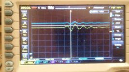
Okay did some more testing, reflowed my current sensor connections twisted those wires too. Added some voltage measurement wires on the two middle 5v inputs, 32 and 11. Only when going into higher amps did I notice a small ringing on the 5v line. Question is whether this is from my external wires picking up the measurement or not. Dip in yellow is 4.65v, time base is 200ns, division of 500mv, blue is 1.0v division both are average of 5.0v.
Maybe some more caps will solve this, but not really too sure.
Just realised is should measure pin 21 also, this is the main supply pin right?
However on a side note it now does not hang up after a FOC measurement. Yet it keeps showing the overflow error. Checked my pwm signals and they looked fine voltage wise on each output. Biggest side note it that with the v2.75 chip the FOC on 100v worked for the remy motor. Will double check with by halving my pack whether it starts working again at 100v with the new chip.
Attachments
Tomdb
10 W
She cooches now, wierd how one version of the chip finds certain caps fine and another not.
Added a 470 uF cap to the pin 20/21 and a 100nF now it does it first try. However, need to keep my amps set to 10, at 20 for foc she does not work. Okay turns out I need to beef up the feed to pin 21/20 more because at 220v it oscillates alot. Which is quite strange, might this be due to some interference from the board underneath?
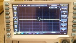
Here is the ringing on the 5v currently, the question now is, is it enhanced by my measurement setup or is it really there.
Sorry for the crap photo, but the wires coming out of the inverter are the 4 different 5 volt rails and ground. In quite close proximity to the three phase wires which are unshielded 25mm^2.
So big lesson here, caps are your friend. will probally rework my current pcb to have the correct cap layout for the future. that is one I aquire a larger power stage
Added a 470 uF cap to the pin 20/21 and a 100nF now it does it first try. However, need to keep my amps set to 10, at 20 for foc she does not work. Okay turns out I need to beef up the feed to pin 21/20 more because at 220v it oscillates alot. Which is quite strange, might this be due to some interference from the board underneath?

Here is the ringing on the 5v currently, the question now is, is it enhanced by my measurement setup or is it really there.
Sorry for the crap photo, but the wires coming out of the inverter are the 4 different 5 volt rails and ground. In quite close proximity to the three phase wires which are unshielded 25mm^2.
So big lesson here, caps are your friend. will probally rework my current pcb to have the correct cap layout for the future. that is one I aquire a larger power stage
Lebowski
10 MW
It's something to do with how the 30F series by Microchip is built. If you run it on a power supply with no caps it just somehow refuses to work. Lots of caps at each of the power pins are really necessary for the 30F to work correctly.... I guess the current taken by the chip is extremely pulsed, so it really relies on having no inductance in the 5V supply lines. The things runs on 120 MHz internally....
You need to have a very short GND connection to the probe, such as when using the GND spring, if possible. The aligator lead is enough to pick up interferences.Tomdb said:Here is the ringing on the 5v currently, the question now is, is it enhanced by my measurement setup or is it really there.
If I measure like this:

I get this (noise at the center is from a basic "triac sine-chop" soldering iron nearby (30cm), the other interferences I don't know):

But if I measure like this:

I get this:

Also, for a "top notch" measurement, if you have unused channels on the scope with probes connected but not measuring anything (even if the channel is OFF on the scope), remove them from the scope or connect their GND clips to the same GND point as the probe that you're using.
Tomdb
10 W
Currently I am starting to doubt that its actually down to the capacitance on the rails. Depending on the way I am grounding my inverter or motor things change alot.
Next test will be to separate the 12v for the power electronics and the Lebowksi board. Maybe it might be needed to take some more EMC reduction steps, kind of a bummer since the board fits really nicely in the original enclosure.
Next test will be to separate the 12v for the power electronics and the Lebowksi board. Maybe it might be needed to take some more EMC reduction steps, kind of a bummer since the board fits really nicely in the original enclosure.
Ground loops can be a bitch. All my digital is isolated from the powerstage.Tomdb said:Currently I am starting to doubt that its actually down to the capacitance on the rails. Depending on the way I am grounding my inverter or motor things change alot.
Next test will be to separate the 12v for the power electronics and the Lebowksi board. Maybe it might be needed to take some more EMC reduction steps, kind of a bummer since the board fits really nicely in the original enclosure.
Tomdb
10 W
Tried many combinations of 5v caps, now there are 100nf cap right on the legs of the IC with an elco attached. Yet the spikes remain, even went through the isolate my ground loops. The only thing still to be disconnected is the Ground reference for the current sensors, this however would mean cutting the pcb into pieces or the pins of the current sensor. Then I would have to run a 5v rail to them, is an option but right now does not feel like my solution.
Biggest thing is I have identified that the frequency of the rail osculations are matched to switching frequency or double the switching frequency. Also at 110v there are oscillations but they are accepted by the Lebowski Ic, to note some setups of inverter heatsink ground motor case ground and powersupply negative will result in a resetting of the Lebowski IC. If anyone has any advice in finding a solution it would be greatly appreciated.
Thing right now is, I do not plan on using this inverter in an application above 200v, might even decide to settle for 100v. I will be getting a new powerstage for my 300-400v build, so spending loads of time on this setup is not too beneficial.
Tomdb
10 W
I cut the current sensors free from the main inverter pcb and hard wired them directly to the lebowksi board. Still at 220v with completly isolated lebowski board it does not work.
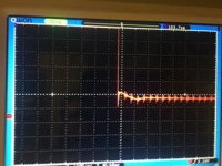
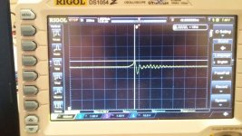
Now at 110v it does still work, and produces this wave form on the 5v bus. 200ns/div so an oscilation of around 12.5mhz, could add some more 100nf caps to try and solve it on the pin.
Now at 110v it does still work, and produces this wave form on the 5v bus. 200ns/div so an oscilation of around 12.5mhz, could add some more 100nf caps to try and solve it on the pin.
Attachments
Tomdb
10 W
Some more tweaking today. No real progress to report. Kind of lost now, problem might now slowly be becoming that I am making a mess of it.
If in theory it is due to the 5v on the pins being unstable then different levels of current (thus duty cycle) should not have any effect on this. Turns out it does not, currently at 160v trying to run soc at 3 amps it completes with the overflow error. run it at 10 amps it does not complete, IC resets during measurement. This does indeed cause me to ponder whether there actually is an issue with my 5v rail.
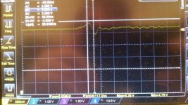
This is the worst voltage pin, barely hits 4.78v
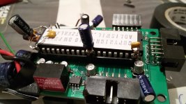
Current state of the board, 100nf smd caps on pins and more caps all over.
If in theory it is due to the 5v on the pins being unstable then different levels of current (thus duty cycle) should not have any effect on this. Turns out it does not, currently at 160v trying to run soc at 3 amps it completes with the overflow error. run it at 10 amps it does not complete, IC resets during measurement. This does indeed cause me to ponder whether there actually is an issue with my 5v rail.

This is the worst voltage pin, barely hits 4.78v

Current state of the board, 100nf smd caps on pins and more caps all over.
Futterama
1 kW
Tomdb, do you have any long wires that could pick up noise from the motor and cause the reset? Maybe a bad connection somewhere?
Also try using SMD MLCC capacitors instead of those electrolytic ones. You can get 22µF 10V X7R in 1206 package which would fit the DIP pins of the controller IC.
A small tip for you scope, you can insert an USB stick and press the printer icon to save a screenshot from the scope, it is much more detailed than a photo of the screen. Notice that you might want to make sure the USB stick is formatted to FAT16 or FAT32. I'm using an older 1GB Kingston stick, that worked better than some of my newer higher capacity Sandisk sticks.
You can also try an "old" patch Tomdb. Feed the uC's positive rail through a schotky diode and then a 100uF+ "decoupling" cap (keeping the uC's 100nF pin decoupling caps, of course). This prevents transient drops in the "global" supply rail from affecting the sub-circuit after the diode, where the "big" cap holds the rail during the drop transient.
Anyways, 4.78V is within the usually acceptable supply range of 5V parts (typically from 4.5V to 5.5V)...
Anyways, 4.78V is within the usually acceptable supply range of 5V parts (typically from 4.5V to 5.5V)...
Similar threads
- Replies
- 3
- Views
- 970
- Replies
- 10
- Views
- 1,308
- Replies
- 31
- Views
- 2,259
- Replies
- 12
- Views
- 7,028


