Low voltage DC inverter for more speed ?

Hyena

10 GW
Joined
Aug 13, 2008
Messages
6,222
Location
Sydney, Australia
Hey guys,
has anyone tried using a low voltage DC DC inverter / step up transformer to get more speed out of their motors ?
I know I'll lose current/torque but I'm wondering if the increase in voltage would be worthwhile ? Even if it's a step up from say 36 to 60v ?

I'm trying to get more speed without having to add another tonne of batteries (I'm doing it on the cheap using SLA)

Is this doable or a silly idea ?

Cheers

Jay
 
Hi Jay,

It is doable, and its not a silly idea. Well, I have to say that, because I've done it.

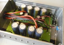
P1010736DCDC.JPG

This is DC-DC converter that I used for an experiment to make 36 V batteries deliver a constant 43 V, even under load. Most DC-DC converters are step down rather than step up, and most are lower current than we need for motors, so I ended up building this one myself.

Nick
 
I think it's a pretty cool idea. Like Tiberius said, it's not common to find step-up DC/DC converters, but I like the idea of more speed if I need it.
 
Hyena said:
I know I'll lose current/torque but I'm wondering if the increase in voltage would be worthwhile ? Even if it's a step up from say 36 to 60v ?
You'll take an efficiency hit too.

If you have enough batteries to compensate for the current demand, you might be better running them in series.
 
Yeah that's the trade off, the expense for extra SLAs is relatively minimal but its a question of whether the extra weight makes it worthwhile.
As stated, having looked around step up DC DC converters don't seem to easy to find.

Tiberius, your solution looks like a good one :)
Is it mainly just the transistors and capacitors shown there or is there more to it ?
I'm guessing it'd be easy enough to modify the same design to step up the voltage a little higher ?
 
Hyena said:
Tiberius, your solution looks like a good one :)
Is it mainly just the transistors and capacitors shown there or is there more to it ?
I'm guessing it'd be easy enough to modify the same design to step up the voltage a little higher ?

There's a bit more to it, surface mount components under the board, but its not completely rocket science. So far its a prototype design, the output voltage can be changed easily enough and the components are theoretically good up to about 100 V.

I'm still working on it and I'll post more in due course. Right now I'm having to line up some more test equipment to handle the currents involved.

Nick
 
Tiberius said:
This is DC-DC converter that I used for an experiment to make 36 V batteries deliver a constant 43 V, even under load. Most DC-DC converters are step down rather than step up, and most are lower current than we need for motors, so I ended up building this one myself.
Nick
Wonder if your step-up dc-dc converter uses booster circuitry?
 
The7 said:
Wonder if your step-up dc-dc converter uses booster circuitry?

Hi,

Yes, it is a standard boost topology at the core, but its set up with a few differences. For instance, the outputs can just be connected in parallel without diodes to add the currents up, and multiple input batteries can be connected without diodes.

Nick
 
Yeah they sound like a cool device, but at 600+ POUNDS they're waaaay out of my budget. I was hoping for a solution that came from a handful of parts and soldering iron :lol:
 
Tiberius,
A step up converter typically makes use of large inductors to store the energy in a magnetic field. One way to avoid this is to make use of a charge pump step up converter, which only uses capacitors, but typically this can only be used in lower current applications.
I don't see any great big honking inductors in your design ... are you using a charge pump topology? If so, how well is it working? Let us know the details!
 
The black things in the corners are the inductors. I was going to wind my own but I found these that claim to be designed for the purpose, and they work. Interestingly, as the current requirement goes up, the inductance needed goes down.

Nick
 
How about using a switch that activates a bank of relays (to handle the high amperage). The relays can toggle the connction between multiple battery packs from parallel to series to deliver speed boost. Has anyone tried that yet?
 
read my response on the evforum

http://www.evforum.net/forums/showthread.php?t=990

Finding a high current (above 50A) converter is going to be hard to do.... at least not for under 600 bucks

I'd focus on finding more smaller batteries that allow you to have the same Wh pack, but at a higher voltage/lower Ah setup.
 
Sacman said:
How about using a switch that activates a bank of relays (to handle the high amperage). The relays can toggle the connction between multiple battery packs from parallel to series to deliver speed boost. Has anyone tried that yet?
I have done that using a switch. Works fine, but is a bit hard on the input caps to be changing back and forth very often - and you can't do it on the fly.
 
At first, that seemed silly, but now it kind of makes sense. Usually, the battery current at the "equilibrium speed" is less than what they give throughout their operating current range, so there's untapped "power" that could be made use of by upping the voltage through the appropriate converter. So it definitely seems possible. I'd imagine there'd be an efficiency hit but I don't know what it is for boost-up converters and the relationship between efficiency and whatever boost-up variables.

Personally, I'd construct the appropriate circuitry such that you could switch between regular mode(Little efficiency loss, though I don't think inductors can keep their energy for arbitrary time periods like capacitors so if inductors are required, that assumption may be invalid.) and "booster" mode so you could retain the best of both worlds, on demand. Higher torque and higher speed, when needed. It'd be like "electronic gearing", so to speak.(Now I've heard that term before... now where did I hear it?).
 
Tiberius, any update on how well it's working?
I'm interested in building one myself..
 
xplo5iv said:
Tiberius, any update on how well it's working?
I'm interested in building one myself..

Xplosiv,

Good question. The bike I was using the DC-DC on is currently broken, and the other one starts with 72V, so I haven't done anything with it for a while. But I do now have the test equipment I was talking about, so I may do some work on it.

I've got myself some 40 V, 25 A variable power supplies and a nice 50 A electronic load, so I can now run these things up on the bench.

Nick
 
swbluto said:
I'd imagine there'd be an efficiency hit but I don't know what it is for boost-up converters and the relationship between efficiency and whatever boost-up variables.

You'll take the efficiency hit in several ways.

First, speed. Higher voltage = higher base speed = more wind drag = more watt-hours per mile.
Second, switching losses. Capacitances charge and discharge as you switch, and the switches don't operate instantaneously.
Third, inductor losses, both in the copper and in the core.

A much better idea would be to do this inside the controller. Phase advance gives you the same thing (higher speed at lower voltage) without the hit of an extra inductor/FET assembly.
 
billvon said:
swbluto said:
A much better idea would be to do this inside the controller. Phase advance gives you the same thing (higher speed at lower voltage) without the hit of an extra inductor/FET assembly.

Yeah, I understand the basics of switching and inductor losses. I just didn't know what the topology of a "boost up" circuit looks like.

Now, phase advance, you've totally lost me there. I've heard the controller produces a 3-phase AC waveform so I suppose it has something to do with that? Just advance one or more of the phases so two phases over-lap so by wave super-position, there'd be a higher RMS voltage? I don't know the technical details but the idea sounds exotically intriguing.
 
Back
Top