DrkAngel
1 GW
MeanWell Mods
MeanWell Mods - S-150-5
MeanWell Mods - S-150-12
MeanWell Mods - S-150-24
MeanWell Mods - S-150-48
MeanWell Mods - S-240-48
MeanWell Mods - S-350-48
See- ES Wiki MeanWell Mods for more
MeanWell S-150-12

Specs:
*Mean Well S-150-12
*150w max continuous output
*12V - adjustable from 10.6V - 13.2V
(9.63 - 14.38 measured 1 sample)
*12.5A max continuous output@12V -
*12V x 12.5A = 150W
*No fan - Open grid shell - convection cooling
*[http://www.meanwell.com/search/S-150/default.htm Factory Specs]
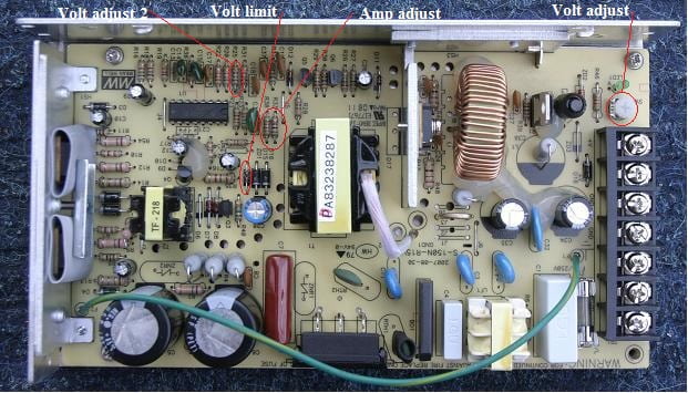
S-150-xx component locations

Problem:
*Rated at 12.5A, but will surge-sustain much higher, burning components
Solution:
*Restrict the amp output -
*The "R33" resister is the key to regulating amperage.
Detailed View

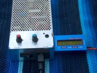
*For testing purposes, I soldered 2 wires of a 2s balance plug to the ends of the R33 resister.
*Then plugged a multi-turn 2K Pot (potentiometer) into the balance connector.
*Then I lowered the voltage to minimum and applied "load".
*Removing and measuring the pot's ohms at each 1/2 amp mark.
*(Pot must be removed to measure! "In circuit" it is laid parallel with 2 other resisters.)
Restricting Current (Amps): R33 mod
Running a resister in parallel with R33-R38 will further limit current
15.8A = OEM 736 ohm
14.9A = 12K
13.8A = 5K
13.5A = 4K
13A = 3.35K
12.7A = 3K
12A = 2.23K
11.6A = 2K
11A = 1.6k
10A = 1.25k
9.9A = 1.1K
9A = 940ohm
8A = 716ohm
7A = 546ohm
6A = 409ohm
5A = 319ohm
4A = 221ohm
3A = 145ohm
2A = 87ohm
1A = 27ohm
Wider Amp adjustment:
Disconnect, or remove R33 & R38.
Replace with adjustable "pot"
Amps ........ Ohms
1A ... from ... 25ohms
2A ... from ... 45ohms
3A ... from ... 75ohms
4A ... from ... 120ohms
5A ... from ... 170ohms
6A ... from ... 235ohms
7A ... from ... 312ohms
8A ... from ... 358ohms
9A ... from ... 406ohms
10A ... from ... 453ohms
11A ... from ... 505ohms
12A ... from ... 550ohms
13A ... from ... 600ohms
14A ... from ... 650ohms
15A ... from ... 700ohms
16A ... from ... 750ohms
17A ... from ... ohms
18A ... from ... ohms
19A ... from ... ohms
20A ... from ... ohms
21A ... from ... ohms
22A ... from ... ohms
23A ... from ... ohms
24A ... from ... ohms
25A ... from ... ohms
*etc.
*Need lower voltage high drain rig to determine higher amps.
** Not precise ... used analog ampmeter.
Widening the voltage range:
*By changing the value of the Voltage pot, I was able to lower the output range substantially.
*Sample tested as 9.66V - 14.40V
*1K = 9.24 - 14.32V (oem)
*2K = 7.36V - 14.32
*5K = V
*10K = V
*
*Running a 1k resister in series with the oem 1k pot should give me a V - V range as a dedicated 1s Li-ion charger.
*As I will demonstrate later, there can be great advantages to lower voltages.
Note! The higher value pots (10K etc) only allow a very "coarse" adjustment at the high voltage end. Harder to fine adjust.
Lowering Voltage
*Lowering voltage could take advantage of higher amperage.
*Without removing components, amperage is regulated below ~?Amps.
*R33, combined with it's neighbor R38, have a measured resistance of ~???ohms.
*Removing both and replacing with a 2K pot allowed me to produce a ?A supply.
*(?K setting. Will compile a chart for higher amperages.)
*
*
Raising Voltage?
*Not tested ... or recommended!
*This model has 15V caps!
150 Watt!
*To be safe and effective, amperage should be adjusted as voltage is altered.
*Volts x Amps = Watts
*Watts should equal, or be slightly below, 150 watts.
*15V x 10.0A = 150W
*14V x 10.7A = 150W
*13V x 11.5A = 150W
*12V x 12.5A = 150W
*11V x 13.6A = 150w
*10V x 15.0A = 150W
*9V x 16.6A = 150W
*8V x 18.75A = 150W
*7.5V x 20A = 150W
*7V x 21.4A = 150W
*6V x 25A = 150W
*5V x 30A = 150W
*4V x 37.5A = 150W
*3V x 50A = 150W
*2V x 75A = 150W
*Yeah ... I'm gonna try pushing everything to the limits ... and then a little further!
(Will test to confirm)
Component Locations
In Series
----
*"In series" is when the negative of one power supply is run through the positive of another - combining their voltages.
Important
*When run in "series" the DC "negative" must be isolated from the 110AC negative ... on all but the primary unit!. Otherwise, the DC positive from the primary unit will "short" through the AC negative on the secondary unit.
'''The negatives are usually connected through the "ground".'''
*3 points of "ground" to remove.
*The external ground - terminal 3.
*The green wire, at F1 near terminal 3.
*The bottom of the circuit board, under screw hole next to fuse. (Cut circuit traces, or insulate with ... fiber, or nylon, washer and screw?)
* The case can be "properly" grounded by connecting the AC ground wire to the removed green wire directly.
MeanWell Mods
S-150-5
S-150-12
S-150-24
S-150-48
S-240-48
S-350-48
MeanWell Mods - S-150-5
MeanWell Mods - S-150-12
MeanWell Mods - S-150-24
MeanWell Mods - S-150-48
MeanWell Mods - S-240-48
MeanWell Mods - S-350-48
See- ES Wiki MeanWell Mods for more
MeanWell S-150-12
Specs:
*Mean Well S-150-12
*150w max continuous output
*12V - adjustable from 10.6V - 13.2V
(9.63 - 14.38 measured 1 sample)
*12.5A max continuous output@12V -
*12V x 12.5A = 150W
*No fan - Open grid shell - convection cooling
*[http://www.meanwell.com/search/S-150/default.htm Factory Specs]
S-150-xx component locations
Problem:
*Rated at 12.5A, but will surge-sustain much higher, burning components
Solution:
*Restrict the amp output -
*The "R33" resister is the key to regulating amperage.
Detailed View
*For testing purposes, I soldered 2 wires of a 2s balance plug to the ends of the R33 resister.
*Then plugged a multi-turn 2K Pot (potentiometer) into the balance connector.
*Then I lowered the voltage to minimum and applied "load".
*Removing and measuring the pot's ohms at each 1/2 amp mark.
*(Pot must be removed to measure! "In circuit" it is laid parallel with 2 other resisters.)
Restricting Current (Amps): R33 mod
Running a resister in parallel with R33-R38 will further limit current
15.8A = OEM 736 ohm
14.9A = 12K
13.8A = 5K
13.5A = 4K
13A = 3.35K
12.7A = 3K
12A = 2.23K
11.6A = 2K
11A = 1.6k
10A = 1.25k
9.9A = 1.1K
9A = 940ohm
8A = 716ohm
7A = 546ohm
6A = 409ohm
5A = 319ohm
4A = 221ohm
3A = 145ohm
2A = 87ohm
1A = 27ohm
Wider Amp adjustment:
Disconnect, or remove R33 & R38.
Replace with adjustable "pot"
Amps ........ Ohms
1A ... from ... 25ohms
2A ... from ... 45ohms
3A ... from ... 75ohms
4A ... from ... 120ohms
5A ... from ... 170ohms
6A ... from ... 235ohms
7A ... from ... 312ohms
8A ... from ... 358ohms
9A ... from ... 406ohms
10A ... from ... 453ohms
11A ... from ... 505ohms
12A ... from ... 550ohms
13A ... from ... 600ohms
14A ... from ... 650ohms
15A ... from ... 700ohms
16A ... from ... 750ohms
17A ... from ... ohms
18A ... from ... ohms
19A ... from ... ohms
20A ... from ... ohms
21A ... from ... ohms
22A ... from ... ohms
23A ... from ... ohms
24A ... from ... ohms
25A ... from ... ohms
*etc.
*Need lower voltage high drain rig to determine higher amps.
** Not precise ... used analog ampmeter.
Widening the voltage range:
*By changing the value of the Voltage pot, I was able to lower the output range substantially.
*Sample tested as 9.66V - 14.40V
*1K = 9.24 - 14.32V (oem)
*2K = 7.36V - 14.32
*5K = V
*10K = V
*
*Running a 1k resister in series with the oem 1k pot should give me a V - V range as a dedicated 1s Li-ion charger.
*As I will demonstrate later, there can be great advantages to lower voltages.
Note! The higher value pots (10K etc) only allow a very "coarse" adjustment at the high voltage end. Harder to fine adjust.
Lowering Voltage
*Lowering voltage could take advantage of higher amperage.
*Without removing components, amperage is regulated below ~?Amps.
*R33, combined with it's neighbor R38, have a measured resistance of ~???ohms.
*Removing both and replacing with a 2K pot allowed me to produce a ?A supply.
*(?K setting. Will compile a chart for higher amperages.)
*
*
Raising Voltage?
*Not tested ... or recommended!
*This model has 15V caps!
150 Watt!
*To be safe and effective, amperage should be adjusted as voltage is altered.
*Volts x Amps = Watts
*Watts should equal, or be slightly below, 150 watts.
*15V x 10.0A = 150W
*14V x 10.7A = 150W
*13V x 11.5A = 150W
*12V x 12.5A = 150W
*11V x 13.6A = 150w
*10V x 15.0A = 150W
*9V x 16.6A = 150W
*8V x 18.75A = 150W
*7.5V x 20A = 150W
*7V x 21.4A = 150W
*6V x 25A = 150W
*5V x 30A = 150W
*4V x 37.5A = 150W
*3V x 50A = 150W
*2V x 75A = 150W
*Yeah ... I'm gonna try pushing everything to the limits ... and then a little further!
(Will test to confirm)
Component Locations
In Series
----
*"In series" is when the negative of one power supply is run through the positive of another - combining their voltages.
Important
*When run in "series" the DC "negative" must be isolated from the 110AC negative ... on all but the primary unit!. Otherwise, the DC positive from the primary unit will "short" through the AC negative on the secondary unit.
'''The negatives are usually connected through the "ground".'''
*3 points of "ground" to remove.
*The external ground - terminal 3.
*The green wire, at F1 near terminal 3.
*The bottom of the circuit board, under screw hole next to fuse. (Cut circuit traces, or insulate with ... fiber, or nylon, washer and screw?)
* The case can be "properly" grounded by connecting the AC ground wire to the removed green wire directly.
MeanWell Mods
S-150-5
S-150-12
S-150-24
S-150-48
S-240-48
S-350-48