pegaz666
10 µW
Hello all!
I’m not confident to draw conclusions myself hence this request for your help.
I have just built my malectrics v4 spot welder a bit modified as I’m using 2x FET boards in parallel instead of just one. So I have 12 FETs in total. On top, instead of using the original Infineon mosfets from the project I have used Fairchilds which are used in kWeld spot welder (I saw a higher peak power in their datasheet so I thought since kWeld is a reputable device it will make mine even “stronger” and better?).
To power the welder I use 3s CNHL Lipo 10.000mah 100C (200C burst). I may need to use something more powerful hence 2FET board as to do my 0.1mm pure copper + 0.15mm pure nickel sandwich it takes around 45ms of pulse time. I’d like to go lower with the time to reach ~20ms region.
Someone told me that one gate driver IC is already maxed out to fill 6 gates of original fets while I’m using here 12 fets so I should consider using a second MCP to drive the 2nd FET board independently so that each MCP drives one FET board. Of course I’d need to add extra capacitors for the 2nd MCP. That person wasn’t sure if the second MCP will be really needed for this application though so I was advised to do some oscilloscope measurements to justify that fact but after doing so I didn’t hear anything back from him regarding these graphs…
For your convenience I’m attaching datasheet for FETs used here and MCP gate driver:
kWeld FET:
Gate driver:
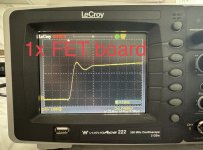
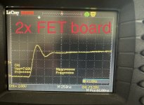
Below are the results at same scope setting 1 FET board vs 2 FET boards:
25ns:
50ns:
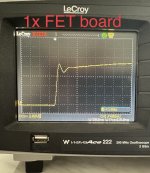
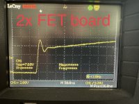
500ns:
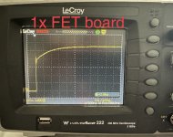
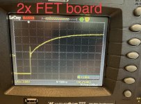
From the above i can see myself that for some reason Miller Pateau effect occurs just below 6V if using 2 FET board versus just below 8V when using a single FET board… No idea why such difference and which one is “better”?
The next observation is more obvious: for the gates to reach the full voltage it takes longer when using 2X FET board.
1FET= ~3500ns vs 2FET= ~5000-6000ns?
Again not sure if this is a “problem” in this application or not? I will be doing my welds 5 seconds apart or so.
Shall I be concerned about the above results using my welder with 2FET board and one MCP driver? Original creator said it’s okay for max 2 FET boards but the other person wasn’t so sure hence all the confusion… I just need to be sure that my welder is as reliable as possible.
Last question:
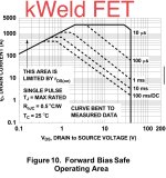
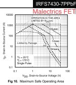
Did I do well by using the kWeld’s FETs instead of original from the project? (Here is a datasheet for the original Infineon mosfet for this project: https://www.mouser.pl/datasheet/2/196/Infineon_IRFS7430_7P_DataSheet_v01_01_EN-3363302.pdf )
kWeld FET:
Malectrics FET:
I’m not confident to draw conclusions myself hence this request for your help.
I have just built my malectrics v4 spot welder a bit modified as I’m using 2x FET boards in parallel instead of just one. So I have 12 FETs in total. On top, instead of using the original Infineon mosfets from the project I have used Fairchilds which are used in kWeld spot welder (I saw a higher peak power in their datasheet so I thought since kWeld is a reputable device it will make mine even “stronger” and better?).
To power the welder I use 3s CNHL Lipo 10.000mah 100C (200C burst). I may need to use something more powerful hence 2FET board as to do my 0.1mm pure copper + 0.15mm pure nickel sandwich it takes around 45ms of pulse time. I’d like to go lower with the time to reach ~20ms region.
Someone told me that one gate driver IC is already maxed out to fill 6 gates of original fets while I’m using here 12 fets so I should consider using a second MCP to drive the 2nd FET board independently so that each MCP drives one FET board. Of course I’d need to add extra capacitors for the 2nd MCP. That person wasn’t sure if the second MCP will be really needed for this application though so I was advised to do some oscilloscope measurements to justify that fact but after doing so I didn’t hear anything back from him regarding these graphs…
For your convenience I’m attaching datasheet for FETs used here and MCP gate driver:
kWeld FET:
Gate driver:
Below are the results at same scope setting 1 FET board vs 2 FET boards:
25ns:


50ns:


500ns:


From the above i can see myself that for some reason Miller Pateau effect occurs just below 6V if using 2 FET board versus just below 8V when using a single FET board… No idea why such difference and which one is “better”?
The next observation is more obvious: for the gates to reach the full voltage it takes longer when using 2X FET board.
1FET= ~3500ns vs 2FET= ~5000-6000ns?
Again not sure if this is a “problem” in this application or not? I will be doing my welds 5 seconds apart or so.
Shall I be concerned about the above results using my welder with 2FET board and one MCP driver? Original creator said it’s okay for max 2 FET boards but the other person wasn’t so sure hence all the confusion… I just need to be sure that my welder is as reliable as possible.
Last question:
Did I do well by using the kWeld’s FETs instead of original from the project? (Here is a datasheet for the original Infineon mosfet for this project: https://www.mouser.pl/datasheet/2/196/Infineon_IRFS7430_7P_DataSheet_v01_01_EN-3363302.pdf )
kWeld FET:

Malectrics FET:

Last edited:

