Allex
100 MW
Hm I can only see your cap, where is the inductor?
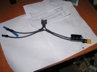
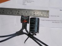
ridethelightning said:inductor 22uh, 30A is in the bottom pic, black, square with gold copper winding, on the positive lead that goes to the phase wire
sorry for bad pictures, it was all done in a rush

ridethelightning said:yes that is the inductor you see.
I did not see it in the picture lol.
madin88 said:it looks alot smaller than the one adaptto sells. maybe you mixed up milli henry and micro (µ) henry
ill post a forsale thread.....used....undersized adaptto inductor...... 


sardini said:Thumps up for carbon plate!
of course, only if i can make them sure fit into these cases.madin88 said:sardini said:Thumps up for carbon plate!
have to figure out how to make the plates removeable with waterproof sealing. maybe i'm able to install them to the hinges of the case.
22s12p 2500mAh cells would give me less voltage sag and about 2400Wh x 85% = 2000Wh usable juice
sardini said:Just cut the top of the lid (keeping the locking mechanism ) and use the appropriate glue , to glue the plates. Do you have any battery store in mind that delivers in the european countries and the taxes are already included ? i hate to pay customs fee.