
torqueboards
1 MW
@mantas - what do you think the 1.22mm plywood can support as in weight wise (battery, esc)?
Mantas said:Ttw said:Hi !
Can you give us more detail about your arduino setup ?
Is it wireless ?
Yes it it wireless - Bluetooth.
I've looked over this thread a couple times now ... there's much good stuff in here.torqueboards said:@mantas - what do you think the 1.22mm plywood can support as in weight wise (battery, esc)?
Mantas said:Here is a source code for new controller algorithm.
Features:
Dynamic acceleration - faster in the beginning, slower in the end.
Speed hold function - If "Z" button is pressed speed value are saved and board keeps the speed without joystick. And using joystick you can increase or decrease hold speed (like Metro - board)
Fast acceleration option - if "C" button is pressed acceleration is fast all the time.
After a test ride with new algorithm I still see some things that needs to be improved... so keep tracking my posts if you are interested.
SOURCE :
#include "Wire.h"
#include "Wii.h" // Library for Wii Nunchuck
#include <Servo.h> // Library for controlin Servo or ESC
WiiChuck chuck = WiiChuck();
Servo myservo;
int speed_val; // Speed value
int speed_val_cur = 60; // Current speed value
int y = 0; // Jaystick value
int time = 200; // Delay timer
int speed_val_hold; // speed value which will be holded while Z button is pressed
void setup() {
Serial.begin(115200);
chuck.begin();
chuck.update();
myservo.attach(9); // ESC attached to 9 pin of Arduino
}
void loop() {
// If you hold down Z button of Nunchuck you accelerate faster
if ((chuck.buttonZ)||(chuck.buttonC)) {
if (chuck.buttonZ) {
Serial.print(" Z ");
//time = 100;
speed_val_hold = speed_val_cur; // Sets speed value to hold
}
// If you hold down C button of Nunchuck you accelerate slower
if (chuck.buttonC) {
Serial.print(" C ");
time = 100;
}
} else {
time = map (speed_val_cur,60,80,100,250);
speed_val_hold = 60;
}
delay(time);
chuck.update();
y = chuck.readJoyY();
// Maps the joystick value to the speed value (max speed 130) max posible 179
Serial.println();
speed_val = map(y, 0, 119, 62, 130);
// This is what hapens in case we loose a Blue tooth conecction
if (y > 122) {
speed_val = 60; // 60 means - no speed , motor stoped
speed_val_cur = 60; // 60 means - no speed , motor stoped
speed_val_hold = 60;
}
// This is whats hapens then we again have BT signal, it just restarts everything
if (y == 124) setup();
if (y <= 0) {
speed_val_cur = 60;
speed_val = 60;
}
if (speed_val_cur < speed_val) {
speed_val_cur = speed_val_cur + 1;
}
else speed_val_cur = speed_val;
if ((speed_val_hold > 60) && (y > 0) ) speed_val_hold++; // If hold button is pressed and joistic moved up - increase speed
if ((speed_val_hold > 60) && (y < 0) ) speed_val_hold--; // If hold button is pressed and joistic moved down - decrease speed
if (speed_val_hold > 60) speed_val_cur = speed_val_hold;
myservo.write(speed_val_cur); // Here we control ESC
//----- Printing to screen to see results ---------
Serial.print("Joy = ");
Serial.print;
Serial.print(" ");
Serial.print("Speed = ");
Serial.print(speed_val_cur);
}
torqueboards said:Hi Mantas,
I like your wooden design for the battery case. Wonder, if it can actually bend decently? I have a 2 motor, 2x 8000mah battery packs that are pretty thick. I went and got Midwest Thin Birch Plywood 1/32" x 12" x 24" but it ended up cracking on me. I'm looking to get a thicker and heavier duty size.
Is the 1/8th (3.175mm) inch and/or 1/16 inch (1.58mm) better?
torqueboards said:RF - I got the http://www.utrechtart.com/Midwest-Thin-Aircraft-Grade-Birch-Plywood-12-x-48-in-Sheets---4---3mm-Thick-MP58276-i1016200.utrecht the 1/32in.
Would the 1/16 inch be a better plywood? As the 1/32 inch was nice and flexible but bent under pressure on a fold and cracked at the screwed in areas.
1/16in is 1.58mm and Mantas mentioned he had 1.22mm aircraft plywood. Only issue being is that his doesn't have an extreme bend like mine. I'm using 2x 8000mah 5s batteries which stand 69mm high.
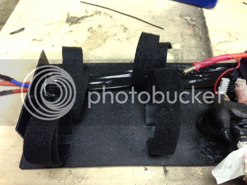
torqueboards said:I found out that for my battery case, I found some industrial adhesive velcro which is holding all my electronic parts onto the board and found it works great. It actually holds my battery in place pretty well. I am however, going to add either cardboard and/or 1/64 Birchwood Aircraft Model Plywood (because of it's flexibility) to the bottom, it can actually flex around the parts. I am also going to just velcro the board/cardboard to the bottom of my board instead of drilling holes since the velcro holds so well and the parts will not be leaning on the board anyways since they are also attached with velcro.
rf said:torqueboards said:I found out that for my battery case, I found some industrial adhesive velcro which is holding all my electronic parts onto the board and found it works great. It actually holds my battery in place pretty well. I am however, going to add either cardboard and/or 1/64 Birchwood Aircraft Model Plywood (because of it's flexibility) to the bottom, it can actually flex around the parts. I am also going to just velcro the board/cardboard to the bottom of my board instead of drilling holes since the velcro holds so well and the parts will not be leaning on the board anyways since they are also attached with velcro.
More photos please.


carlboyscout said:Hey mantas, I had a question about the code you used to program your arduino. I have never programmed on an arduino before, and I was wondering if you could post the libraries and the actually code, you have used. I am using an arduino micro as well. Thanks for all your help!
Carl Demolder
.Mantas said:About the hills, I am having one problem that do not allow me to go into steep hill - motor belt is slipping through a smaller cog. I am trying to make this belt mote tight but Alien drive kit is little bit not ok for my cog, cause I have a very small one (12 tooth). so now I am trying to adjust this kit, but maybe it is better just to order a 15 tooth cog. Maybe someone is experiencing the same problem ??? and have a solution...