N.E.S.E. the no solder module

Nice. Subscribed.
 
When will you do the build video of the 20sXp battery pack? That will give us a better idea for the final size of a completed pack.
 
agniusm said:
I just broke one tab on a single bend. It is so brittle after nickel plating that i don't know what to think. It was ok on the previous design as there were no bends to be made but here it just wont do. Will do tin plating to see how better it is.

How about this :
For the area you intend to bend on the tab : cover with waterproof tape.
Then plate with nickel layer.
Remove tape
The whole bussbar is now plated exept where the bussbar was covred with tape. Remove tape.
Bend the bussbar on that zone (copper but no plating) wich is not so brittle.
You can always apply a light amount of flux anf the solder tin on the unplated spot after bending
 
I think tape just won't do. I am not plating myself and as I understand the prices involves heat. Let me get new tabs, plate them with tin and do another test.
The cells are new, they had one cycle with previous 14s6p setup.
 
Hey Agniusm,

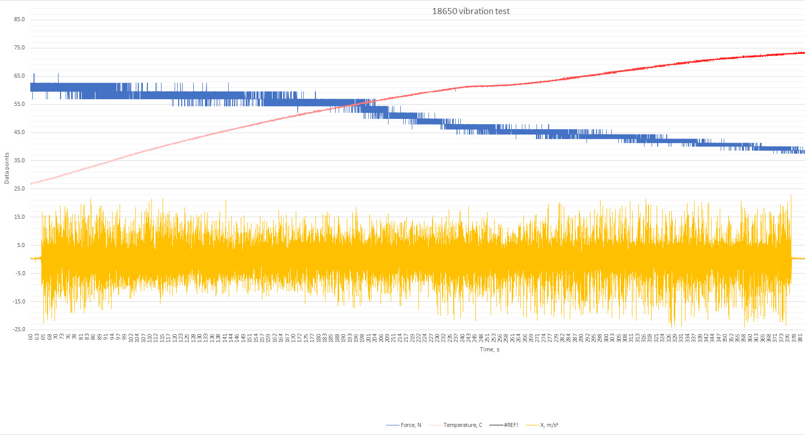
I rewatched your video and noticed that your voltmeter is placed across you load instead (nichrome wires) of the NESE's post.
So although the math being my calculation is right, the numbers might be a bit off...
I mean the resistance is not just from NESE and cells, but from NESE, cells and Big cables....
I'd reconduct the test with voltmeter on NESE's post instead of nichrome wire resistor...

What gauge wire is in the clampmeter and what lenght ? Is that pure copper welding cable or CCA cable ???
If it is 4AWG, if you use 2 meter (4 meter roundtrip at 113.9Amps, voltage drop around cabling would still be around 0.37 Volts, so that wil you see 3.440V on multiter, the actual voltage on NESE post would be 3.81 V !
I used this too : http://www.calculator.net/voltage-drop-calculator.html?material=copper&wiresize=0.8152&voltage=3.81&phase=dc&noofconductor=1&distance=2&distanceunit=meters&amperes=113.9&x=72&y=15

So if it's like my example here (4AWG, 4 meters roundtrip, putting power would result in smaller voltage drop : from 4.132V@0A to 3.81V @113.9A.
Meanind dV = 0.324 at 113.9A.
So total resistance of 2.84 mOhm. Alsmost entirely due to the cells themselves....

Matador
 
Thanks for the calculations.
I could not place multimeter on NESE cause i was using my shaker in the beginning and was no way to attach probes. Wires would make no more than 2 meters round trip but i could measure resistance of those wires which could be taken into consideration. Wires i used are from electric forklift truck, copper and they don't say what gauge. I could measure them as well.

As you can see my setup is nothing fancy, doing it at home with no fancy lab equipment, using resources i have.
I do have Hantek DSO5202P oscilloscope which i can use next time.

On the plating. I don't do it myself and i assume there is a lot of heat involved so tape could not work and plant might not do it cause tape would bring contaminants into environment. Let me do Tin plating and i will run test again, will try to attach probes as close to the cell as possible. As i mentioned before it is easy to anneal nickel plated copper with heat but most wont do that and most will not need every "microgram" of resistivity shaved off.
 
agniusm said:
measure the resistance of the cables and it is 0.3ohm per cable. Cables are 33.18m2 so probably 2.3AWG.


Multimeter are not designed to measure resistance much lower than 0.3-0.5 Ohm, because what you measured is in fact the resistance of your multimeter circuitery + multimeter probes.
At 33.18 mm2, for 2 meter lenght, if it's copper (it's resistivity is ρ = 1.68×10^−8 Ohm . m), you can expect that it adds 0,00101266 Ohms of resistance... Using Claude Pouillet's law adn simple formula R = ρ . l/A (https://en.wikipedia.org/wiki/Electrical_resistivity_and_conductivity ). So 1.01266 milliOhm is far too low to be measured with multimeter...
Still, at a very heavy INITIAL load of 113.9A ---> dV = R x I means VOLTAGE DROP because of wire part (not cells or NESE part) is dV = 113.9A x 0.00101266 Ohm = 0.115 V
And at the end of the experiment FINAL LOAD of 75.9A --> dV = 75.9A x 0.00101266 Ohm = 0.077 V

So the real voltage at the NESE post could be assumed to be :
INITIAL : 3.440 V + 0.115 V = 3.555V @ 113.9A
FINAL : 2.892 +0.077 V = 2.969 V @ 75.9A

Of course, this is still an approximation, the real way to do it would be to hook voltmeter to NESE posts directly.
I won't redraw the whole graph extrapolation, but knowing the new wire info, you started more at 92% SOC and finished more at 10% SOC.
At 92% SOC, resistance of LG HE2 seems more like 25.0 mOhm than at 75% SOC where it was 23.4 mOhm or at 8% SOC where it was 17.8 mOhm.
So for 6P cells in theory = 4.166 mOhms (INITIAL at 92% SOC) and 2.967 mOhm (FINAL at 8% SOC).

Anyways... Rough estimate but a bit refined with cable data now :

INITIAL
NESE empty box at ambiant temp Resistance (1S6P) = 6.093 mOhm (experiment) - 1.013 mOhm (cable) - 4.166 mOhms (6Cells at 92% SOC) = 0.914 mOhm

FINAL
NESE empty box hot at 62°C Resistance (1S6P) = 6.152 mOhm (experiment) - 1.013 mOhm (cable) - 2.967 mOhms (6Cells at 8% SOC) = 2.172 mOhm

So all in all, each 6P-NESE module would add in itself between 0.914 to 2.172 mOhm to the cells in parallel (6 cells).

Minus 3.0 mOhm from 6P cell's intrinseque resistance (betwenn 4.2 and 3.0 mOhm depending on SOC).

Knowing that, if I 'd make a 14S6P pack with HE2 cells, the solderless module would add 12.8 to 30.4 mOhm to the cells IR (58.3 mOhm to 41.5 mOhm depending on SOC).
SO all in all, a 14S6P pack of HE2 with 14 6P-NESE modules would total 71 mOhm @ 92%SOC [14 x (4.166 mOhm + 0.914 mOhm)] to 72 mOhm at 8% SOC [14 x (2.967 mOhm + 2.172 mOhm)]


So pulling 30A on that 14S6P 71 mOhm pack, the voltage drop would be from 57.88V (4.134V per cells) to 55.75V.... A 2.13V drop @ 30A load on that 6P pack ( dP = R x I = 0.071 Ohm x 30A) and heat lost would be 64 Watts (dP = dV x I = 2.13V x 30A), while the remaining 1672W would be injected into the eBike controller ( P = V x I = 55.75 x 30A)...

PS : For resistance calculations, I assumed the big cable was exactly 2,000000 meters long roundtrip. Again, best way to do it is measure voltage right at thge NESE module post... Crude estimate here). You see how such a small factor mad a big change on calculated resistance of 6P-NESE empty module resistance values from my post above.... Almost half less. Good thing we know about the cable...

Good stuff !
Matador
 
OK. I'll do the test when I get my bus bars tin plated so we can account for that and I got my rig beefed up with more as wire for higher amps. I also made ring terminals so I can hook multimeter strait to the module. I have 6 of other lg he2 cells stripped from PVC shrinkwrap. Also ordered fsr402 sensor to get full pack of data.
Will have to wait and see.

What could measure lower resistance? Anything could be obtained for not much money?
 
agniusm said:
What could measure lower resistance? Anything could be obtained for not much money?

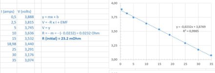
The voltmeter + the ammeter you have are pefect for the job. The best way to measure a very small resistance is to use an indirect method (measuring voltage drop at different current loads... when you plot voltage in fonction of the amps, the slope of the graph wil give you the average resistance value).
No need to buy a 4000$ Hiroki meter...

Best way to do it : measure voltage drop at different load values. From voltage drop (dV) and amp (I) values, you can calculate R from ohms law.... But to be more precise do a multiple point analysis (take masures of different voltage drops at different load values). Take video filming amps and volts at same time.

Than you can make a graph and get very good regression correlation....
The only think that's really important to take voltage reading at the NEVE module post so we know exactly the resistance of module by substracting the resistance of cells themselves. This methodes eliminate a third variable, that is, the resistance of the big wire cable that goes to the nichrome load.

Your volmeter is already very good...¸
You have to take voltage drop values at different current load to get the resistance. Make a graph and deduce R of NESE with cells.

R of NESE without cells = R of NESE with "Brand-X" cells - R of parralled "Brand-X" cells.
Knowing the empty modules resistance, you can anticipate the resistance of the pack with any sort of cells when you know the resistance of that particulare "Y-cell".

The precise why is doing the graph like I did... The most point, the better the precision.
Also you have to mesure delta-V (dV) every time, because the voltage dip is due to internal resistance, but also because of normal cell discharge.test.jpg

Matador
 
agniusm said:
OK. I'll do the test when I get my bus bars tin plated so we can account for that and I got my rig beefed up with more as wire for higher amps. I also made ring terminals so I can hook multimeter strait to the module. I have 6 of other lg he2 cells stripped from PVC shrinkwrap. Also ordered fsr402 sensor to get full pack of data.
Will have to wait and see

Awesome !
 
I have chinese lcd ammeter with shunt. I wander if that would work better than my clamp meter? I could hook up oscilloscope as well if need be but i dont know how accurate it is. guess I could compare it against fluke.
 
agniusm said:
I have chinese lcd ammeter with shunt. I wander if that would work better than my clamp meter? I could hook up oscilloscope as well if need be but i dont know how accurate it is. guess I could compare it against fluke.

Most error margin will not stem from the meter, but from the fact that at higher loads, voltage drop will not only be the real voltage drop (originating from internal resistance) but also normal discharge of cell.... You have to take that into account.

Rather than ploting V in fonction of I
Plot dV in fonction of I...... Knowing V under no load (zero amps) will not climb out the the inital voltage after you remove the first load experiment you apply.
you have to remeasure V (no load) each time you add a new load to make sure that dV only represents voltage drop and not cell discharge.
The faster you take the measure, the better.... that's because when you'll put high loads (ex :20A/cells), the cell discharges very fast so you have to take the two measures (V and A) very quickly.... I recommend filming the two meters (V and A) at the same time, that way you can playback at low speed and catch the two values at the same time.

Your 3 voltage digit voltmeter is not the limiting factor here... That's more than enough.
Also, I trust you DC clamp meter more thant the chinese diplay.
Not that I don't trust chinese stuff, the problem is you dont know if the ammeter shunt they use have been calibrated to strict standard, loosly calibrated or not calibrated at all... they dont give certificate of calibration.

On the contrary, your clampmeter most likely has been calibrated. Ideally, meters are most accurate when you measure something around 2 thirds of the display scale they use (alsolute error in units is the same, but relative error (in % of units) is less).
 
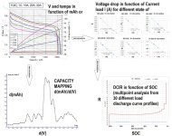
In the ideal would, someone would invent a device...
Put the cell inside

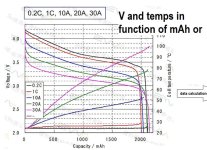
Then it draws discharge curves (and temps) with V in fonction of mAh for every possible discharge load (0A, 1A, 3A, ..., 30A).
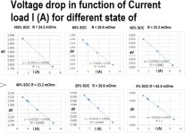
Then it calculates resistance doing the method I did with the regression graphic (V = - r . I + emf) for every different possible SOC.
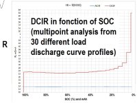
Then it would make a graph of DCIR in fonction of mAh (SOC).

If somebody invents this... I'm buying. It would need to be pluggable to a computer.


Imagine... 0A, 1A, 2A, ... 30A. You get 30 different curves of V vs mAh
Then for any SOC (ex : 100%SOC, 90%SOC, 80%SOC).... for any one SOC, you get 30 datapoints (x=I ; y = V) and each resistance value you get for each SOC is made buy calculating the slope with a 30 point graph regression analysis.

That gadget would rock !

If the Device could draw all the graphs at after a few hours... I'm shure justin could design such a sophisticated device for eBike enthousiast and professionnal battery builders : What I mean in pictures :
Synopis_Matador concept.jpg1.jpg2.jpg3.jpg4.jpg


Matador
 
I'll post some pics soon as the grandkids go home. Just received two modules, and I am impressed. The business model has the customer having the modules 3D printed locally, which is a brilliant choice. Also, assembly and configuration of the pack is done by the customer, which hopefully...will prevent any lawsuits if operator error causes a fire.

The design will improve over time, but they are a great design right now. I have a 4P and a 6P module, and the plastic is surprisingly rigid.
 
Thanks mate. You are spot on with liability ;)
I have a new test setup, this time in my mans cave. How low can i go is my question. I will try to run a heavy load and knowing that cells bounce back, how low can i drain them to be sure they gave all? 2.5V, 2.0V?
 
Did look at the vid. Nice work.

So INITIALLY you had : 4.192V no-load and 3.395V@159.6 A, which is 3.395V@26.6A per cell (6P pack)
FINALLY it finished at : 2.314V@91.8A, which is 2.314V@15.3A per cell.
Recoverd to 2.950 after test (and still rising 1 mV per 2-3 seconds)…

I placed these values on the graph (se my previous post) to extrapolate values.

From volt-amps reading you have INITIALY (about 100 % SOC), there is 4.994 mOhm resistance (0.797V drop @ 26.6A).
From graph, DCIR of cells is 26.2 mOhm @ around 100% SOC, theoretical. So 6P pack 4.372 mOhm theoretical.
This means at close to 100% SOC, the NESE module only adds 0.622 mOhms ! Wow, that awesome.


From volt-amps reading you have FINALLY (about 0 % SOC), there is 6.928 mOhm resistance (0.636V drop @ 91.8)… is very inacurate at less that 20% SOC charge as graph voltage decline abruptly and I'm sure cell resistance is way more than 23.3 close to 0% SOC.This is a crude estimate, and also not that the recovery voltage (no load) was still rising and not totally stable when camera stopped (But let’s say 2.950 – 2.314 = 0.636 V drop slight underestimate).
From graph, DCIR of cells is 23.3 mOhm theoretical @ 0% SOC (probably very inacurate estimate at that part of the graph since voltage is declining so abruptly). So 6P pack 3.389 mOhm theoretical (i'm sure theoretical value is way more than that nearing 0% SOC)

So all in all, each 6P-NESE module would add around 0.622 mOhm to the cells in parallel (6 cells). This time, the calculations are not affected by the long cables, as the voltmeter is checking voltagge drop directly onto NESE module posts.

Although my calculations are crude, 0.6 milliohms for one 6P empty NESE pack is close to adding almost no resistance to the intrinsec internal resistance of the cells themselves. For each 23.3 mOhm cells, NESE only adds 3.6 mOhm per cells (six in parrallels is 3.8 mOhm of 6P cells + 0.6 mOhm of 6P connector metal).

i think it is safe to say that the NESE encasing systems (with all it's intrinsec connectors) is in the 1.0 ± 0.5 mOhm range (my calculations are a bit crude), but the number or order of magnitude number seems like what's coming out of my few previous posts, after eliminating the parasitic effect of long cables on calculation.

Again, really impressive Agniusm. This is a breakthrough!
BTW, I'm not surprised by the 75°C considering you pushed the cells over the top at 26.6 Amps/cell... :twisted:
 
I said i want to :D
Anyway, i am blown away myself. 120A per 6P is not too shabby at all. I mean you can dry cells at this rate and NESE connections are way lower than cells them selves which means in this system, only limiting factor is cells, not the kit. I am happy camper now.
 
agniusm said:
I said i want to :DI mean you can dry cells at this rate and NESE connections are way lower than cells them selves which means in this system, only limiting factor is cells, not the kit. I am happy camper now.

I'm also totaly convinced that now the only limiting factor is the cells themselves now since resistance of this kit is so low.
I'm pretty sure even spotwelded nickel strip would perform poorly in comparison to NESE solderless kit! I love it !

Matador
 
agniusm said:
P.S. when i connected module for recharge it was coming up on iCharger at 2.97V so your calculations are pretty close.

OK ! So if 2.97V no load at 0% SOC instead of 2.950V, the drop is 2.97-2.314 = 0.656 V drop with 91.8A.
That is a resistance of 7.146 mOhm total @ 0% SOC. Meaning if you substract the theoretical 3.889 mOhm of 6P @ 0% SOC (extrapolated from graph), NESE pack has 3.257 mOhm resistance.
The thing is, after less than 20% SOC, voltage decline is so abrupt that the throretical resistance of cells if probably way higher than 23 mOhm (so way higher than theoretical 3.889 mOhm for 6P at 0% SOC).
I consider that the graph method is not good below around 20% SOC... Cells DCIR resistance is supposed to rise way more than that....

For example, here is a high-drain VTC4 cell DCIR profile... se how the cell's DCIR is supposed to rise exponentially when it gets closed to 0% SOC :
 
Could you provide also expected weight fully assembled per cell?

For example, on a 50 cell battery, how much weight does the kit add? And what about 200 cells?

Thanks
 
Back
Top