Nextonever
1 µW
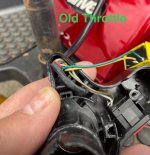
Need help in connecting new throttle with mismatched wires. Any help would be greatly appreciated. Old throttle Broke,so I ordered one from China!
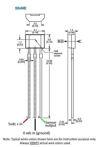
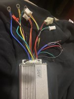
Seven pin twist throttle,forward, reverse,fast and slow. brushless, controller 36 v, 350
Old throttle colors
Red, Blue, White
Olive, Gray
Yellow, Green
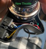
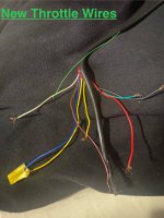
New throttle from China- 3 speed, forward and reverse 8 pin throttle
New throttle colors
Red, Green, Black
Brown, White and Blue
Yellow, Yellow
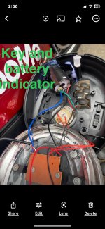
Colors on controller that have connectors are:
Blue, Yellow, Green- motor
Red, Black- Battery
Red, Orange, Black
Yellow, Blue, Black, Green, Orange
Yellow/Green, Black
Pink, Black
Other wires W/O connectors:
Gray, Black, Purple, Black
Red, Black, Green
I tested all components and each passed and are in working order.
When I went to connect new throttle somehow I connected it correctly and it worked. Issue was the wires were too short. So I took it apart again, because I was going to extend the wires .
Here is we’re the Problem is: I did not mark what wire went where ?such as what goes to :
Black
Gray
Purple
Black
I attempt to connect and nothing is working. I don’t know what else to do. Frustrated due to I have mobility issue and I have not been able to do anything.
I have attached photos. Thank you again.
Seven pin twist throttle,forward, reverse,fast and slow. brushless, controller 36 v, 350
Old throttle colors
Red, Blue, White
Olive, Gray
Yellow, Green
New throttle from China- 3 speed, forward and reverse 8 pin throttle
New throttle colors
Red, Green, Black
Brown, White and Blue
Yellow, Yellow
Colors on controller that have connectors are:
Blue, Yellow, Green- motor
Red, Black- Battery
Red, Orange, Black
Yellow, Blue, Black, Green, Orange
Yellow/Green, Black
Pink, Black
Other wires W/O connectors:
Gray, Black, Purple, Black
Red, Black, Green
I tested all components and each passed and are in working order.
When I went to connect new throttle somehow I connected it correctly and it worked. Issue was the wires were too short. So I took it apart again, because I was going to extend the wires .
Here is we’re the Problem is: I did not mark what wire went where ?such as what goes to :
Black
Gray
Purple
Black
I attempt to connect and nothing is working. I don’t know what else to do. Frustrated due to I have mobility issue and I have not been able to do anything.
I have attached photos. Thank you again.
")