Need opinion : Designing a 7s14P in a small box 11*9

marine7

10 mW
Joined
Feb 11, 2020
Messages
24
Hi guys,

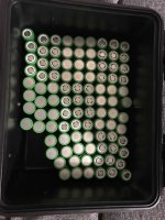
Just looking at option with the perfect flaw for the 7s14P I have a small box and Im limited with the way I can use the box.
Application: trolling motor, step down converter for 12v phone charger
Amperage draw: 18A max
29.4V and 42Ah

Application 1:
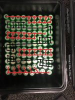
IMG_4299.jpg

or Just two 7s7p on top of each other with one bms ?

Thanks
 
Im assuming you've tried rotating 90deg and getting 14cells in one run... Whilst it's not the ideal layout for high amp draws, your ~0.4c draw should be fine. Just make sure you have as many series connects as possible and that you pull the power out evenly at the pos and neg end ie. run a fat copper wire right across the ends or bring one smaller gauge wire out for each cell and join them all up to the main lead.
Don't forget to insulate the +ends, insulate between P groups. If you're gluing it together, a light sand with 240grit of the sides of the cell really helps the glue stick.
7s7px2 is going to be annoying to build, I wouldn't bother.
 
Thanks for your input, I had the same feeling today when I add the cells, the series connection is not strong.

I have rearrange the cells now in the 12cells shape and I think this will be optimal in the series and the parralel connection.

Let me know what you think.

IMG_430.jpg
 
In this layout, you have only room for 3 connects ( with standard nickel build) where you have to join the next row. That's 6 amps per connection which is still OK with 0.2mmx7mm nickel.
The first layout had room for 7 at the worst point.
You could solder some copper strip or wire over the nickel to help share but as I said given the mild draw that's not really necessary.
And there's 8 groups now?
 
Yeah I will have to update the layout to get 7s not 8s

Is there a better option that what I tried ?

Thanks
 
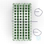
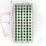
id make it 7s14p, spot weld it together but between 4s and 5s id leave an extra 1/4 inch gap and fold it back onto itself. you can put 1/4 inch neoprene or something in between the sandwich. your positive and negative would be right next to each other. bottom would be 4s, top would be 3s. so you would have that extra space for bms and wiring.
 
goatman said:
id make it 7s14p, spot weld it together but between 4s and 5s id leave an extra 1/4 inch gap and fold it back onto itself. you can put 1/4 inch neoprene or something in between the sandwich. your positive and negative would be right next to each other. bottom would be 4s, top would be 3s. so you would have that extra space for bms and wiring.

What I understood is to build one side as 7s14p, and then fold it on top of itself, the back will be spot weld as 7s 7p and connect 0,2,4,6 with Maybe 14awg?

basically just fold them together and connect them as 7s14p ?
Cheers
 
kdog said:
Get a different box? :D

I have two options
One box is able to get two 7s7p stacked on top or sides
Or the other options is the 11in one side and 9 in the other

Limited with boxes as the either waterproof, or the space is critical.
Ill have to make it work at the end :)
 
84C3F17E-A855-48EA-B6D3-6D1F106921AC.jpegBC660DA4-90CE-4FD6-930C-9346E1E92460.jpeg
goatman said:
id make it 7s14p, spot weld it together but between 4s and 5s id leave an extra 1/4 inch gap and fold it back onto itself. you can put 1/4 inch neoprene or something in between the sandwich. your positive and negative would be right next to each other. bottom would be 4s, top would be 3s. so you would have that extra space for bms and wiring.
 
the other way.

two rows of 7 makes 1p

4p and 5p are connected in series with the spotwelded nickel strip and its just folded back over on itself

HK47q0g.jpg
 
Back
Top