New Kelly pseudo FOC controller series

SplinterOz said:
izeman said:
today i installed JST connectors to connect it to my motor and throttle. the battery/phase wires are VERY stiff as already mentioned. even though they are absolutely up to the task i guess i will change them for super soft silicone wires as the original ones are very hard to bend.
what shall i say: it was a pretty straight forward install. connect phase wires, hall wires, throttle, find a correct combination and you're set. i was expecting some kind of "auto learn hall combination", but nothing like that - or i didn't find it.
there is some "angle sensor identification" but i don't know what it is for.
also compared to those new grin tech controllers, i must say, there is not a lot to configure. you can set throttle range, max current, max speed and some other trivial things. but nothing "sine wave" or "foc" related. on the other hand this may be good, as i wouldn't know what to set anyway :)
so that's it for the moment. the motor is running, but i didn't test the controller on the bike. this may take some more time.


The instructions I got was to set the "Identification Angle" to 170 and write to the controller. Turn off then on. It will then to an auto learn... wait until it has finished and the LED start flashing. Turn off then on. Read the settings again and you should see the "Identification Angle" is some other value.

That is the extent of the functions of Auto Learn.

Yes,it is right.Most of setting about FOC are done by Auto_Identification angle in user program.
 
izeman said:
for those interested, and that don't have the controller yet to try out the software i made this short review. when you click a changeable field/value there is a comment field explaining the setting. this is what i c&p below. those are not MY words.

View attachment 2
Low Volt: The min voltage of reporting this fault - Range 18~80
Over Volt: The max voltage of reporting this fault - Range 18~80
Current Percent: Phase Current Percent. Range: 20~100
Battery Limit: Battery Limit Current, Limit the max value of Battery Current. Range: 20~100
Identification Angle: If read data is 85, the normal operation of the said. In 170, and then restart the controller will automatically into a state of identification Of Angle sensor, after the succes of the identification will be automatically reset to the data in 85, the state of the normal operation. Range: 85~170
TPS Low Err: Hall active pedal, if lower than the value, report the fault of TPS Type. Range: 0~20
TPS High Err: Hall active pedal, if higher than the value, report the fault of TPS Type. Range: 80~100
TPS Type: TPS Type, 1:0-5V, 2:Hall active pedal. Range: 1~2
TPS Dead Low: TPS Dead Zone Low. Range: 5~20
TPS Dead High: TPS Dead Zone High. Range: 60~95
Max Speed: Max Speed [rpm]. Range: 0~10000
Max Fwd Speed %: The forward speed of the percentage of maximum speed. Range: 20~100
Max Rev Speed %: The reverse speed of the percentage of maximum speed. Range: 20~100

View attachment 1
Motor Poles: Motor Poles, The pair pole number*2. Range: 2~128
Speed Sensor Type: Speed Sensor Type, 2:Hal, 3:Resolver, 4:Line Hall. Range: 2~4
Resolver Poles: Resolver Poles, The pair pole number*2. Range: 2~32
Motor Temp Sensor: Motor Temp Sensor, 0:None, 1:KTY84-130 or 150. Range: 0~1
High Temp Cut Out °C: Motor High Temp Cut Out, nominal value 130°C. Range: 60~170
Resume °C: Motor High Temp Resume Temp, nominal value 110°C. Range: 60~170


RLS_TPS Brk %: RLS TPS Braking Percent, the percent of Releasing Pedal BRK in max braking. Range: 0~50
NTL Brk %: NTL Braking Percent, the percent of Neutral Braking in max braking. Range: 0~50
Accel Time: Accel Time, the time of TPS Torque from 0 to max, accuracy 0.1s, 5 is equal to 0.5s. Range: 1~250
Accel Rls Time: Accel Release Time, the time of TPS Torque from max to 0, accuracy 0.1s. Range: 1~250
Brake Time: Brake Time, the time of Brake Torque from 0 to max, accuracy 0.1s. Range: 1~250
Brake Rls Time: Brake Release Time, the time of Brake Torque from max to 0, accuracy 0.1s. Range: 1~250
BRK_SW Brk %: BRK_SW Braking Percent, the percent of BRK_SW in max braking. Range: 0~50
Torque Speed KP: Speed Percent Kp in Torque Mode. Range: 0~10000
Torque Speed KI: Speed Integral Ki in Torque Mode. Range: 0~500
Speed Err Limit: Speed Error Limit in Torque Mode. Range: 50~4000

most settings are self explaining, but i don't understand why they still use abbreviations in the comment field which should be there to make clear what the value is about. there also is some "standard value" missing. so once you change it and haven't written down the original values they are lost. i didn't find a "reset" button or some way to save profiles.
so the software still has some room for improvement.
feel free to comment or ask ...


Torque Speed KP: Speed Percent Kp in Torque Mode. Range: 0~10000
Torque Speed KI: Speed Integral Ki in Torque Mode. Range: 0~500
Speed Err Limit: Speed Error Limit in Torque Mode. Range: 50~4000
These three parameters are for PID adjustment.
If the acceleration of motor is very very strong,you may just adjust them to a lower value.

Yes,we still have many jobs to do for KLS controller.For example,we need to upload configuration demo on website.
Thanks for suggestions.I posted on forum so as to save emails reply.
 
SplinterOz said:
I never had a hall/phase problem with this setup it just ran.
That said when I wanted to reverse the direction I just swapped two phase wires, did the auto identification (not sure I had to) and it spun the right way.
You don't have to swap two phases.It is too much work.
There is an item in the first screen.It is called Change direction.You can choose this one.And do identification again,you will get the expected direction.
 
izeman said:
SplinterOz said:
I never had a hall/phase problem with this setup it just ran.
That said when I wanted to reverse the direction I just swapped two phase wires, did the auto identification (not sure I had to) and it spun the right way.
maybe you got the correct combination by chance? i'll have to retry that. i can't imagine that someone build a controller in 2015 that doesn't have hall-auto-mode.
for the direction change you could have checked the "change direction" check-box in the vehicle tab for reversing the direction :)
Identification angle=Auto_Identify=Hall-auto-mode which can get the correct hall/phase combination by software.People don't have to try 36 combinations.
And KBS-X/KEB/KBL/KHB has the auto identify function also.
As of KLS,you may check whether the auto_identify function is executived successfully or not.
Please check all hall angles are updated in app.
By default,KLS is supposed to work with hall sensors.It is 2 in speed sensor type.
2:Hall sensors, 3:Resolver, 4:Line Hall.
Line hall is Sin/Cosin speed sensor.Usually there are four wires from the motor.+5V,Sin,Cosin,GND.For example,ME1115 from motenergy is this type motor.But the zero crossing point is at 3.0V while other motors with sin/cosin speed sensor are at 2.5V for zero crossing points.
The Resolver is for PMSM motor.The resolver has six wires.It is more complicated than BLDC motor with hall sensors.
Kelly KPS is designed for PMSM motor with Resolver.But the APP or user program is the same.That is why you can see Resolver in speed sensor type item.Please don't choose 3 for KLS controller.
 
There is a pull-up resistor on 12V circuit inside the controller.That is why it is about 10.5V.It is normal.
And this 12V is only useful for switch or LEDs signals.Can not be used to power other devices such as main contactor,brake lights.
The main relay is based on the coil which is hooked up between PWR and pin9.
 
madin88 said:
i also noticed the problem with the braking. i asked fany and she answered it mostly depends on the battery. after i doubled the Ah (and lowered resistance by half) it worked much better.
still strange because even with the small battery i have not seen more than 1V increasing in voltage during regen, but maybe spikes have been much higher and the controller did cut out because of this, but thats only a guess..
There is an option ABS in user program of KBS or KHB.Please enable it so that the regen will not quit at low speed.

But if the motor is too small,it is hard to detect the back EMF in accurate way.It may still quit at low speed.
And it is also related with the detection sampling type.The KBS controller is used to calculate the value by using internal resistance of Mosfets.This is not accurate at low speed.But it is hard to add hall device to detect the current in mini case controller.
 
circuit said:
SplinterOz said:
circuit said:
We had this issue in various setups, from small bicycles to electric car... Explanation about battery is not true or at least incomplete.
This is a serioaus issue and would be great to know what to expect before ordering.


Ok I just tested by turning on the RLS_TP Brk % value to 5.
That means Release of Throttle Position Sensor Brake percent.

At any RPM with no load the motor is instantly stopped.

That seems to be very good news!.
Thank you very much, this is great news.

One more thing I would like to know.. Is it possible to select other type of throttle, I mean "joystick"? I am wondering if it will regen when going forward, but joystick is pushed for reverse. We could hack that to separate normal throttle + analogue brake signal to get on-the-fly adjustable braking force.

Joystick is stick shift throttle firmware function on Kelly controller.
The stick shift throttle firmware can be called wig-wag or joystick operation.It is only a software function.It is only useful for electric boat project.
You still can use the common 0-5K pot or 0-5V throttle for the controller.
If you don't add the joystick,you operated the throttle in this way.
The motor speed will increase when the throttle is from 0K to 5K.

If you add joystick for this controller,you will start the motor from 2.5K position.2.6K to 5K is forward.2.4K to 0K is backward.
2.4K to 2.6K is throttle dead zone.You can adjust the throttle dead zone in user program.
Please note the common throttle will spring back to original position if you release the throttle.
Please kindly check the schematic of the joystick function.

If you are talking this function,we are updating it in the new user program or App.Then customers can enable or disable joystick function.It is your choice.
But it is not available on current version.But it can be added if customers really need this function before shipment.It is only useful for new controller order.
And please remind me that you really need us to add joystick function for KLS controller.

By the way,we will add bluetooth function for our KLS controller in near future.In this case,customers can use Phone to program the controller.
 
SplinterOz said:
circuit said:
Fany also told me that it will run up to 70k eRPM.


Me too but my first test was discouraging.
With the new setting it seems believable.
Fany confirmed with me via email that they have tested it to 48k eRPM

Yes,I have to explain.We think most of motors are not so fast.The motor with higher RPM could get less poles,or motor with many poles could get less RPM.
Anyway we set the max output fre at 500 by default in App and user program.This setting affected the speed.
I sent the new App to release this parameter so that SplinterOz can configure it at 1000.
Then we get the higher speed.
If some customers still can not get the expected speed,I can send the special APP for him to configure the parameter,especially for the motor with higher poles number.
We will default it to 1000 in KLS controller from now on for every controller.But it should be still grayed.If this parameter is too high,it could bring bad impact on the motor and controller.
 
wow. thanks fany for taking the time and answering all open questions.
one more suggestion: it would be a good idea to have the factory preset values written down in the config's program comment field. or maybe have a "reset" function at all to set all values to default in case you messed something up completely.
 
Yes,I talked with our software engineer.We think most of configuration jobs are done by Identification function.There are not many parameters in the app or user program.
And some parameters are very obvious.We did add factory setting button in old KEB/KBL Controller.We found this function is easy to get the controller software into hibneration.That is why we removed it.

Thanks,
Fany
 
Hi,

We just updated the manuals by adding all the explanation for settings in GUI.
Please download the latest user manual from the website.
And we uploaded how to use Identification angle function instructions on the website also.
www.kellycontroller.com/support.php

We added Joystick software function and Cruise control function in the latest version for KLS controller.
People can enable or disable joystick or Cruise control in App or PC software.
Hold the throttle at a certain position about 3-4s to get into Cruise control.
Joystick function has an optional to change the direction from forward to backward quickly without delay.
This item is called Change Dir brake.

CAN bus for KLS controller will be available next month.It is broadcast type.
 
izeman said:
thanks fany for updating the manual. i will read through it and post any suggestions and comments here.
is there a new firmware to flash as well? and if so: how is it done?

Sure,it must be the new controller with new feature.
It is the new hardware.Reflash can not work.

By the way,does anyone need Kelly J1 or J2 aviation plugs?
I will offer them for free for a company or reseller in USA.
 
maybe fany should skip that post, and move on, as there will be some surgery done now .... :)

as i said i am going to transfer this controller into a new case which can be fit to my bike as space is limited and all wires are hidden etc. so no chance to keep the old bulky case.

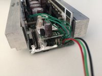
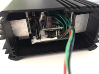
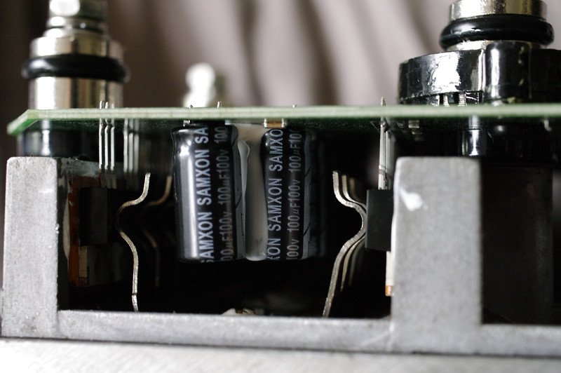
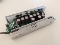
the controller pcb itself it very narrow and long, so i had to source a 15+ FET infineon controller case, and thanks to circuit i got one, and i cut it to length. the infineon case is much wider, so i had to take some 15x20mm aluminium rod and use that as spacer. they were cut to 150mm length and reduced to 14mm height with a mill. then all holes were drilled and it's a perfect fit.

i don't expect any heat issues, as the old small 12 FET kelly controller i have now never gets more than hand warm, and this is a 18 FET and has a temperature sensor as well. so in case it will get too hot there is some thermal rollback. but as i said, i expect it to stay cool. the big aluminium rod will take away heat spikes easily as well and has some serious heat transfer area to the case which is mounted in front of the bottom bracket with a lot of air flow.

here are the pics - please not that this is work in progress, and the screws used are not cut to length and of course new phase wires will be soldered to the FETs, and new battery wires as well.

IMG_0132.JPG
IMG_0133.JPG
View attachment 1
IMG_0135.JPG
next step will be the CA connector and then i can do some real live testing and make the promised "kelly old vs kelly new comparison video"
 
wow it looks really small in that infineon case. nicely done!
 
Nice case you have got there. ;)

Am I seeing this right, are those aluminum-PCBs? Nice and expensive move by Kelly.

I would buy it, but no support for proportional brake is making me go for sabvoton.
By the way, can someone already describe the smoothness and amount of noise and torque in comparison to Sabvoton?
 
sorry. no sabvoton here to compare with.
the only issue i see is, that the kelly's heat sink only connects by two screws at the very outer end. there may be no direct and solid contact to my aluminium bar in the middle section.
what do you think? i thought of placing two screws with insulation through two inner FET's mounting holes. good idea or not?
 
Normally it is being done in other controllers, you just have to make sure the bolt will be well insulated. Also those insulated washers tend to get softer and lose compression under higher temperatures, so that is another thing to consider.
 
circuit said:
Normally it is being done in other controllers, you just have to make sure the bolt will be well insulated. Also those insulated washers tend to get softer and lose compression under higher temperatures, so that is another thing to consider.
i hope that this controller will never be so hot that too high temperature will be a problem for the washers. i tried to buy some today at the local electronics store, but they didn't have them. and they also need to be a bit longer. normally they are only there to isolate the FET from the heatsink directly behind, but i have to drill through this connection plate kelly uses and then tap a thread in the "real" heat sink. we'll see.
 
There's specialized FET springs you can get; the SSC Sabvoton's use them to hold the fets to the (huge) aluminum heatsink body.

i-hXKX99w-L.jpg


Might be able to source something like that to help with thermal contact while staying insulated? Mount it from the top down? Not sure, but worth a shot!

i-pqDZL4q-L.jpg
 
thanks guys. both good ideas.using heatshrink may be the easier way to do it. even though i don't think i need it, as the FET's hole is 3.7mm in diameter. the washer fits into that and takes an M3 screw that is 3mm in diameter. so enough air to not risk a short.
those clamps look nice too, but i don't know where to source, and how to mount them...
 
Digikey or mouser may have them as examples. Also careful mounting a bar across fets as there's a few for each phase; you don't want them all electrically grounded together. The springs push on the plastic package which is why they are the best option. Wish I knew what they were called so you could search for them.

AHA! They are called "Transistor clamps". Google that or look on ebay. What FET's are they? 4110's? Figure out the FET package type and go from there; find clamps that are designed for that style of FET.
 
i have a drill and m3 taper here :) so this is what i did:

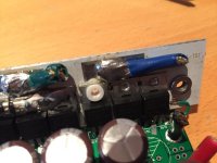
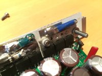
drill through the FETs mounting hole, then remove the heat bar, drill a 2.5mm hole and tap the M3 thread. then opened the hole in the kelly bar to 3.5mm. fitted the washer and all looks nice. no shorts. i did this to the 3rd outer FET from both sides. so there a 4 points where the FETs are fixed to the heat bar and this looks good to me now.

IMG_0139.JPG
IMG_0140.JPG
 
Back
Top