New 'Mini Monster' Programmable Controllers Coming

I went with a 1.2K resistor for R1. I measured 47V on the input to the LM317 with the battery fresh off the charger.

Here is the result of the no-load test on a X5304 motor. The top CA is plugged in to the controller. The bottom one is stand alone and is set up to display RPM (multiply by 10).
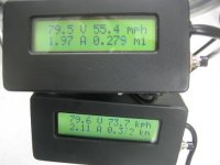
No_Load.JPG

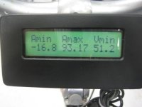
I took it out for a short ride. The throttle response is good (it definitely is not soft start). I noticed the controller cutting out if I gave it full throttle too quickly (when the current reached about 40A). I think this is because the input to the LM317 is dropping too low. I have to release the throttle to recover. It seemed to get worse as the battery wore down.
first_ride.JPG
I don't really believe that max current reading.

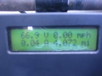
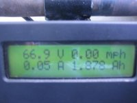
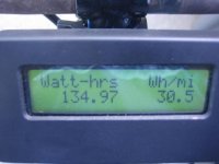
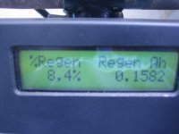
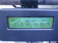
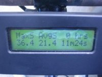
I recharged the battery and moved it and the controller to a different bike. This one has a 9C rear hub. The CA is standalone. I reset it and went for a four mile ride with some hills. I blew by a couple of cyclist climbing the hills :twisted: .
elevation.JPG

I reset the CA before the trip.
9c-1.JPG
9c-2.JPG
9c-3.JPG
9c-4.JPG
9c-5.JPG
9c-6.JPG

I put my hand on the controller a few times throughout the ride and it was barely warm. The battery was heating up though.
After the ride I measured the battery temperature at 146F. The controller case was 95F.

I need to do something about the controller cutting out. It is annoying.
 
That was one of the best posts I have ever seen.
Nice work.

Before you go to the work of geeking the 5V reg try testing without the CA to eliminate that (LVC, over Speed, Over current) and try pushing out all the values in the controller software (maximize the current, minimize the LVC etc). The chip voltage sense mod is also suspect.

Anyhow - nice work. Looking forward to our meeting.

-methods
 
methods said:
That was one of the best posts I have ever seen.
Nice work.

Before you go to the work of geeking the 5V reg try testing without the CA to eliminate that (LVC, over Speed, Over current) and try pushing out all the values in the controller software (maximize the current, minimize the LVC etc). The chip voltage sense mod is also suspect.

Anyhow - nice work. Looking forward to our meeting.

-methods

I tried removing the CA, it didn't change anything. That last ride was with a stand alone CA, so it couldn't do anything to the controller anyway. The settings in the software are already maxed out. The reason I think it is the 5V dropping out is because I have to release the throttle to get it to start again. It's like when you turn on the controller with the throttle open, the motor won't start (it's a safety feature). The current through the 1.2K resistor is 30mA when idle. If it goes up to 50mA when active, that would be 60V drop across the resistor. When the battery sags under load, there won't be enough left to make 5V.
 
stator said:
In order to allow regen, I changed the value of R11 from 7.5K to 11K. Setting the voltage to 75 in the software should give about 87V. This will also change the LVC measurement, so a software setting of 52 should give a LVC of about 60V.

There was some error in my calculations there. That was a ~19% increase, so the 75V regen setting would get a ~90V limit and the LVC should be set to 50.5 to get 60. (Thanks Ben!)
 
stator said:
The reason I think it is the 5V dropping out is because I have to release the throttle to get it to start again. It's like when you turn on the controller with the throttle open, the motor won't start (it's a safety feature).

Ah -> that there is some good logic :mrgreen:
I agree

-methods
 
why not drop your input power resistor back into the 620R range. i think the idle current on the infineons is more in the 50mA range and active current around 63mA.

at 80V idle you would have 49V input to the regulator, and at 60V under full power it would around 21V input to the LM317T. all well in spec.

i have pulled the 12V rail up to 19V and it ran with the stock 300R input resistor. i would not wanna have the 12V rail drop below 9V myself.
 
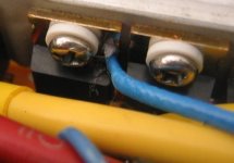
I didn't have a 620 ohm resistor, so I use a 680 ohm. I also cemented a thermocouple to the phase B high side FET.
thermocouple.JPG
It's hard to see it in this picture, but the tip of the thermocouple is between the nylon washer and the plastic body of the FET, touching the metal tab.

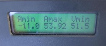
I went out for a ride on the same course. The controller still cut out, but not as bad. The voltage dipped to 51.5V, so it's not surprising.
Vmin.JPG

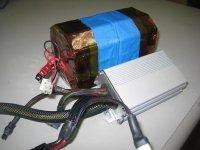
This battery I'm using isn't much bigger than the controller.
controller+battery.JPG

I was climbing the hill at 28MPH with a lot of power. The FET temperature peaked at 89C (starting temp was 31C). I was coasting down the hill at about 30MPH, regenerating, when suddenly the drag increased and I knew I had blown a FET. I had to unplug the motor and turn around to pedal back up the hill. I wasn't laughing at the bicyclists this time :cry: . When I got home, I pulled the controller apart and found the phase B low FET shorted. I guess I will have to revisit that maximum regen voltage limit.
 
"Every act of creation is first of all an act of destruction."
- Pablo Picasso

Great reporting!

Regarding the possible cause of the FET failure:
The regen conditions don't seem to be much of a candidate: '-10A', <90V I assume. Though rated to 100V, 112V has been reported for the 4110s. Do you have a max regen voltage from the CA for that run?
Might be best to disable regen initially to remove this variable from basic testing...
 
BenMoore said:
The regen conditions don't seem to be much of a candidate: '-10A', <90V I assume. Though rated to 100V, 112V has been reported for the 4110s. Do you have a max regen voltage from the CA for that run?
Might be best to disable regen initially to remove this variable from basic testing...

The CA doesn't keep max voltage AFAIK. The battery was still fresh since I wasn't very far into the ride. In order to get 10A flowing back to the battery, the voltage must have been very high. What I did different on this ride from the last one, is I was crouched down to keep the speed up (and regenerating) while going down the hill. Anyway, I will turn off regen for now. I also changed R11 to 9.53K.
 
I have been considering putting a 100V high powered Zener diode across the rail to shunt over-voltage conditions.
They do this in a lot of consumer electronics (like car ECU's) when there is a high likelihood of voltage spikes

That is good reporting though.

-methods
 
A nice, low resistance battery would also be very good at saving your controller from any high voltage regen damage. I'm not sure what that batt in your picture is made of, but it's quite small so would have to be high quality to have a low enough Ri. Personnaly I always charge my Lipos to 4.1V/cell for a number of good reasons, one being that this removes any danger from doing regen right off the charge.

Also take into consideration all the resistive losses between the controller and battery pack when you are doing regen, since all the resistance here makes for extra voltage across your controller when your current is flowing backwards. Method's idea of using an appropriate zener to help protect your FETs might be good to try, but make sure your check our their V vs I curves in the datasheet very well to choose the correct one. Also, zeners will only be usefull to protect your FETs from transient high voltages (aka spikes), but not from continously high voltages.
 
ZapPat said:
Also, zeners will only be usefull to protect your FETs from transient high voltages (aka spikes), but not from continously high voltages.

Actually most zeners have a special feature that not everyone knows about to alert you to "continuously high voltages".
It is called a "smoke signal". Similar to that used by Native American Indians to convey a message over long distances, this smoke signal (along with a distinct smell) can often times alert the user to the dreaded "continuously over voltage" situation. The special feature is reusable but only if you capture all the magic smoke and put it back in the zener.

For voltage spikes that have an average power lower than the rating of the zener, you dont have to worry about capturing the magic smoke :D

-methods
 
ZapPat said:
I'm not sure what that batt in your picture is made of, but it's quite small so would have to be high quality to have a low enough Ri. Personnaly I always charge my Lipos to 4.1V/cell for a number of good reasons, one being that this removes any danger from doing regen right off the charge.

I made the battery from two Bosch Fatpacks (Konion). It is 20s2p 18650 cells and I charge it to 83V.
 
I have to use a 25v 6600 uf cap in the input power wires of my car ecu to smooth out the power coming into it and it made a huge difference. I imagine a 160 volt cap could do the same the higher the uf the more it will smooth it out. I think a simple little cuircit should be easy enough to build to stop regen at 100 volts. What do you think methods? I know I want regen for one it is just damb cool and for two I live in a very hilly city!
 
Arlo1 said:
What do you think methods?

We are going to address those issues in the new 18 fet thread - I want to include regen on the 100V controllers.
The micro controller is capable of limiting the regen voltage on its own, I suspect we just have to tune the input correctly. We dont even know that was the cause of the failure.
Stator will probably figure it out before we even get the thread started :mrgreen:

-methods
 
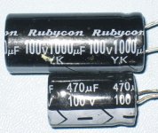
I solved the problem with the controller cutting out by changing the input capacitor (C1) from 470uF to 1000uF. The 1000uF cap is about the same diameter, but longer.
two_caps.JPG

It just fits inside the controller.
View attachment 2

I wanted to see how hot the FETs would get under a constant load, so I chose a path up a nearby hill with some 10% grade.
hill.JPG

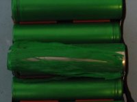
The speed slowed to 12MPH on the steepest part of the hill. The FET temperature peaked at 102 C. While I was coasting back down the hill I noticed the battery voltage had dropped below the LVC and there was no throttle response. I felt the battery and it was warm, but not too hot. I kept riding the rest of the way home (mostly coasting), and when I got home I noticed the battery was a lot hotter and the voltage was lower. I opened the battery pack and found that the plastic on some of the cells had melted and allowed the pack to short in the middle. It killed some of the cells :cry: .
melted.JPG

If anyone is building packs from cylindrical cells, make sure to use some insulator between the cells that won't melt.

I had already decided this battery pack wasn't going to push the limits of the controller, so I had ordered 24s of the Turnigy 5Ah lipo batteries. Hopefully they will arrive in a few days and I can continue testing.
 
methods said:
ZapPat said:
Also, zeners will only be usefull to protect your FETs from transient high voltages (aka spikes), but not from continously high voltages.

Actually most zeners have a special feature that not everyone knows about to alert you to "continuously high voltages".
It is called a "smoke signal". Similar to that used by Native American Indians to convey a message over long distances, this smoke signal (along with a distinct smell) can often times alert the user to the dreaded "continuously over voltage" situation. The special feature is reusable but only if you capture all the magic smoke and put it back in the zener.

For voltage spikes that have an average power lower than the rating of the zener, you dont have to worry about capturing the magic smoke :D

-methods

Just use an amplified zener and no magic will be needed for continuously high voltages (Especially the kind needed to return the magic smoke). Just size up your power transistor/transistors accordingly.
 
Nope.
You guys can thank me for no news :|

I am not sure if it was said, but I shipped the parts out two months ago and USPS lost the shipment.
It was a large expensive order that neither of us could afford to lose.
Unfortunately it was uninsured to save on Duties. That was my decision - so I take responsibility.

An inquire to USPS for a shipment to Australia takes 24 days.
We are coming up on that deadline so hopefully there will be resolution.

We are now working on a second order of parts so it should not be too much longer.

-methods
 
Damn, that sucks. I guess Costa Rica moves one notch up the totem pole. I've always self insured on all shipments too...hundreds of times, and two shipping companies on each, with zero lost items in 12 years, knock on wood.

I hope they get it tracked down and delivered, because I was hoping to get my greedy mitts on a few of those little babies.

John
 
methods said:
I am not sure if it was said, but I shipped the parts out two months ago and USPS lost the shipment. -methods

Not good to hear.

USPS parcels come into Australia and are delivered by the Australian postal system (Auspost).

If you have a reference number (if there's no tracking number) then try calling the Auspost if you get some verification that the parcel left the USA.
 
All of that has been done.
There is no record of the package anywhere.
For all we know a homeless man has it in Indiana

-methods
 
We need to help this man in Indiana to come and join Endless Sphere ....

I sure hope the shipment will be located and we're on track again with this.
 
Back
Top