SwampDonkey
100 W
- Joined
- Mar 27, 2018
- Messages
- 227
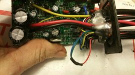
So im working on this again. How can I get the controller to switch on? I have an LCD3 display Im trying to connect so Im guessing the "on switch" will be in the display connector?
flangefrog said:Usually you hold down the middle button connected to the display for a few seconds. This effectively shorts the red and blue wires on the display connector. Remember you will need to have the secondary "switch" enabled by shorting those two wires on your controller (I think you said they were blue/green and yellow)
flangefrog said:Just connect the display to the controller by matching the wire colors, and then short the two wires on the controller like you did before to get the voltage on the regulator output. After everything is connected you can hold down the power button on the display.
SwampDonkey said:flangefrog said:Just connect the display to the controller by matching the wire colors, and then short the two wires on the controller like you did before to get the voltage on the regulator output. After everything is connected you can hold down the power button on the display.
I didnt short any wires. I just have battery voltage coming from both yellow wires. The green and blue are attached (already shorted) on the cable Im assuming isnt the display connector. I'll grab a pic for you.
flangefrog said:It should be the other one - I assume your display doesn't have a white wire?
SwampDonkey said:Im trying to make sure it works before doing a bunch of soldering. Any idea on how I can at least get battery voltage out of the display connector?
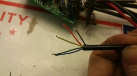
SwampDonkey said:Im getting full battery voltage from the red input wire to the black display wire. Im familiar with continuity hunting. I'll track it down and report back. I dont have a pink lead to short to the red. Can you tell which wire is equivalent on mine?
Edit: Red display wire has continuity with the blue and green wires on the other cable. Weird stuff!
Edit 2: It looks like your pink is my thin blue and green. The thin yellow is your thin red located near battery +, and carries battery voltage (49V) when grounded to the battery - in. It also sparked again when I plugged it in, so the caps are working. This thing might be alive after all!
kuririkura said:Sorry to interrupt, just want to ask about this controller.
If it stated rated current 11A and max current 22A.
Should i have battery with 11A or 22A?
docw009 said:My opinion is that the battery should put more current than the controller requires. You might be in a situation where you really need full power out of your controller. Depends on the battery, but I have seen a half discharged 20A pack shut itself off when I pushed the throttle on a bike with a 25A controller.
In the ebike world, I doubt you could even find a 11A pack, and a 20A pack is considered weak. Most advertise 25A-30A capability and that is what I would recommend.
Don't confuse the rated discharge capability of a pack with the Ah rating. While they go hand in hand, they are not the same units.
With our OpenSource firmware for KT motor controllers, you can set the max values for each of battery and phase currents.Pegazus said:I understood that on the kunteng controller label :
- rated current was the maximum current coming from the battery. It drives the maximum cruise speed.
- max current was the maximum current coming out the controller. It drives the maximum acceleration especially at low speed and it also called max phase current.
But, it does not correspond on how you use this informations for your battery pack.
If I'm wrong, I would be interesting to know how to get the maximum phase current of a kunteng controller just by looking at the tag !
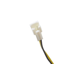
Avitt said:From the aliexpress description, it seems that this connector is for a light switch:
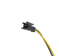
And this one directly powers the light:
But is sounds like you've confirmed this on your own.