Problem: Is it the halls or the controller? Qs or Kelly?

DogDipstick

100 kW
Joined
Aug 19, 2018
Messages
1,857
Location
Fleetwood Pa
I got a problem.. Been getting running resets while riding for the last 25-40 miles. Began slowly, and hall error ( 4.2) shows on the bike.

Kelly KEB 72330.. Just goes into error anymore in a few min.
Qs V1 35H 205 .. sometimes stutters, but usually just drops power on a roll...

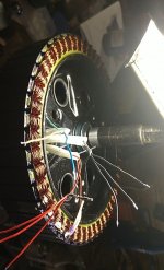
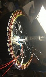
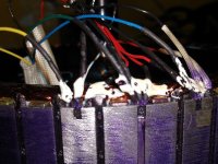
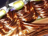
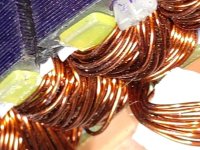
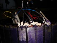
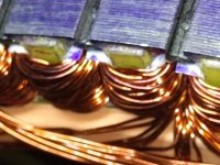
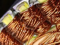
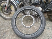
Been hard on the motor, heat and power wise, with high watt high bursts from a 1000w design... but never ran over 3Kw contin..... Pics inside are just fine, no burning discolorations... definitely heated up a good bit though. Ran hot for what mods ad others here recommended... ( Rode hard enough to think to myself.. "Somethings gonna break... ") Jumps, burnouts, doughnuts, endos, banging the hub around on its dropouts. ... Could magnets be moving cause the errors? Something I didnt check...

CA3 with all the bells and whistles. All of them, I think. Alot at least. The 2 Aux, hall pickup speed sensor, TCDM, shunt, logger, dc/dc, the whole 9 yards. I hope ( think i) set it up correctly, it lasted 700 reliably smooth miles before trouble began.

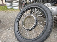
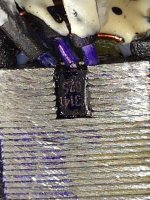
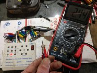
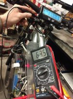
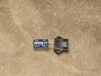
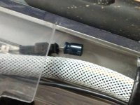
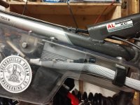
Fixed the Hall sensors, with a new set bought from our fellow forum poster E. Lyen, even though they (OEM halls) were triggering on back-probe fine.. .. what appeared to be correctly, and both with the digital meter and a BLDC tester box. In sequence, all firing. ( ironically I cracked my Tq arm vertically in half almost... , but still held.. I should've taken a pic.. First removal of the rear wheel in 700 miles.. ) all welded up now... )..Both the new and the old acted the exact same way on the tester.

Bike lasted 2 miles, then the resets began again. Still fires all hall sensors in sequence, on the meter and the box. Can ride reliably for about one min. Then any hard bump, or 20-80A+ hit, of fast overrun, and the error pops. Even unloaded.

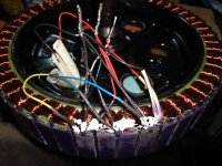
Even just sitting there powered, the error pops when the bike has not moved. Should Hall error pop when no movement is made? Does that mean its in the controller? I went over EVERY bit of wire and connection for shorts or damaged/compromised... twice or more times.

What do you guys think? Kelly, Qs, or the CA3 Krabappel? Even if it just sits there, not moving, I reliably get a Hall sensor error in ten min or so. The controller case is also kinda warm, but that may be normal. The controller was bought used, and worked great, but is old. Like probably 8-10 years old, bought off a forum member here.

Anybody have any Idea as to where igo next? F'in dogs all washed up here. Dont have alot of money.. but I have a 4115 Lyen controller here I could maybe use to rule out the Kelly.. but that is a big big chore.. complete teardown to fit the 4115 Lyen. Also have a new CA3. Getting my ( second ) set of Hall sensors in soon, and going to try to replace them again... IDK if I did something wrong the first time, but they all fire.

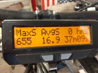
Thank you for anybody that can shed any whim of help here, I am exhausted in testing. i cannot find something wrong. I go over logs... no flukes, except a transient Speed spike to like 655mph every 30-40 logs.... Or the Ca Analogger forgets to record ( fake SD card? Card popped out from bumps? One or the other... ) got a new one now.....Yes this was also happening at the same time as the resets )) or something.. leaves a log out of sequence.. IDK what is happening. Maybe the CA is resetting? IDk. I got it for a tool to test for conditions, and it works good for the most part, I just get that speed spike to unrealistic speeds very now and again.

Tahnk you ANYBOOOOODY. Im at wits end here, gonna buy a new motor in about .... lets say soon. I dont want to. I want to learn what the problem is.

Options: New motor New controller New CA3.. Or fix what I got. I would rather fix what I got. I cant do everything at once, thats for sure, and I need the commuter. Hell, if someone want this motor for 100$, I would do it. Get a new one, with a few more ( hundred certainly) dollars , and rebuild the bike.
 

Attachments

  • problemQS.jpg
    problemQS.jpg
    82 KB · Views: 1,075
  • problemQS2.jpg
    problemQS2.jpg
    121 KB · Views: 1,075
  • problemQS3.jpg
    problemQS3.jpg
    123.4 KB · Views: 1,075
the ca can't cause a hall error...unless you are using the ca-dp connector on the controller (don't think kellys have one?) for the speedo signal to the ca, *and* there is a problem in the wiring somewhere along the way causing shorting of that signal to some other signal or power or ground, etc. if using a separate wheel speed sensor (or no speedo connection) then it's not the ca.

but you could unplug the ca from the entire system just to eliminate it, for thoroughness (i myself wouldn't, at this point, till other things ahve been eliminated).


if the halls are working when not connected to the controller, using a voltmeter and an external pullup resistor (5k to 10kohm) from the signal under test to the power supply being used to test the halls, or using the "ebike tester" unit (which has pullups built in), then the motor is unlikely to be the cause.


the kelly itself could cause the problem if it's internal pullups are not working (bad solder joint, failed resistor, etc); these are probably smd resistors near the mcu or near the hall sensor wire input pads on the pcb.

wiring could cuase the problem if there is a poor contact anwyhere between the hall itself and the controller, either in the actual contacts of the connectors, or connection of wires to pcb pads or contacts of connectors (since you have probably eliminated the actual hall pin wiring connection by replacing them).


sometimes a hall error is caused by excessive electrical noise on the hall lines, so you could try adding a 0.1uf (104) ceramic capacitor from each hall signal to ground (three caps in total), as close to the controller as you can. (inside the controller if you like, but it'll void any warranties, i'm sure).
 
I really don't know but you said, anybody.
everytime ive had a hall error its been the motor cable at the axle, ive gone through 3 motor cables this year, each time I was having problems with my torque arms, you said you cracked your torquearm so have you tried replacing your cable?
my cables looked good but they were bad
 
serious_sam said:
goatman said:
the motor cable at the axle
That was one of my first thoughts too.

I did not go that deep. Is a possibility.

I just tested for basic shorts with a meter. Cant help an intermittent fault, or one that only shows in hot temps. Wires were slightly heated here or there, you can see it in the 3mm^2 insulation.. light marks in the insulation from the wires being press together in the harness. Yes, it did hit the wire a few times on falling over.

Getting another set of sensors atm and will probably upgrade the phase wires and the durability of those signal wires too while I am out at the shop. I may also machine the rotor mount for a deeper bed so the hub cover plate (rotor mount) does not come close to the wire. Looks like I can turn down at least a centimeter here, depending on where the caliper lands. That should clearance for the new wire, and hall signal wire set... The plate just fits on my lathe. I will have to drill the hole out too at that time.

Someone else said this may be a symptom of motor magnets slightly dislodged, but still IDKY I get a error when sitting powered not moving... I would think the controller would need to register something to error out.

amberwolf said:
the ca can't cause a hall error...unless you are using the ca-dp connector on the controller (don't think kellys have one?) for the speedo signal to the ca, *and* there is a problem in the wiring somewhere along the way causing shorting of that signal to some other signal or power or ground, etc. if using a separate wheel speed sensor (or no speedo connection) then it's not the ca.


They ( it, the single hall signal wire, signals for speed to the Ca3) are on the hall sensor, input signal, to the Kelly for speed metering.


if the halls are working when not connected to the controller, using a voltmeter and an external pullup resistor (5k to 10kohm) from the signal under test to the power supply being used to test the halls, or using the "ebike tester" unit (which has pullups built in), then the motor is unlikely to be the cause.

I am using an "Ebike Tester" and got good signals from it both before and after teardown, but same error. when installed on the Kelly.


the kelly itself could cause the problem if it's internal pullups are not working (bad solder joint, failed resistor, etc); these are probably smd resistors near the mcu or near the hall sensor wire input pads on the pcb.

Hence someone told me to try the Lyen, but that is expensive and I dont want to mes it up I guess I need a Milliohm meter to check phases f0r shorts to ground...


sometimes a hall error is caused by excessive electrical noise on the hall lines, so you could try adding a 0.1uf (104) ceramic capacitor from each hall signal to ground (three caps in total), as close to the controller as you can. (inside the controller if you like, but it'll void any warranties, i'm sure).

I thought this might explain my phantom speed readings from time to time.. but I still am boggled.


EDIT: I just did the 5 miles of my normal commute one way.. and on 20A limit and 1500W peak, 800w contin, I got the whole way without an error. Only on the last 1/4 mile, on 3Kw, uphill for a bout 30 seconds, ... did the error pop. Immediate error. Rode what felt was fine for the first 4 1/2 mile. Something has got to be getting hot and bothered. I havnt a clue.
 
DogDipstick said:
They ( it, the single hall signal wire, signals for speed to the Ca3) are on the hall sensor, input signal, to the Kelly for speed metering.
then try disconnecting that wire from the ca3, so that it is eliminated as a possible source of issues.

it is unlikely, but kellys are known for sometimes having hall issues whenever there is interference.

usually if the ca3 speedo wire were causing the problem, you would have problems with speed readings too, either no readings, or wierd overspeed indications (hundreds of mph) or zero speed, whenever you were also having hall issues, etc. or the hall would just stop working, and the ca3 would die of a fried mcu, if the hall were being shorted to something like battery voltage (which happened on one of mine, from an external shunt wiring fault at the exit of the cable from the molded shunt body).

I am using an "Ebike Tester" and got good signals from it both before and after teardown, but same error. when installed on the Kelly.
that means the halls themselves are unlikely to be a problem...but wiring still could be, because the ebike tester does not apply votlages to the phase wires like the controller does, so induced voltages in the hall wires from the phase wires when connected to the controller could cause noise the kelly can't handle. direct shorts to the phase wires would likely kill the halls *and* the controller (and the ca3 if it were on the same hall as the speedo wire).

Hence someone told me to try the Lyen, but that is expensive and I dont want to mes it up
the "lyen" controllers i've seen (and got) are just generic controllers that are a bit beefed up, and sometimes with better fets than generics. they dont' do anything special, unless he's changed his products quite a lot (unlikely). there's nothing fundamentally different about them from any generic controller you could get for $50-$100 or less, depending on the power levels you're after, except that few of the cheap generics end up being programmable at all, and the lyens i've had and seen do have some minimal things you can change a little bit. and that you have lyen to ask questions of, and some warranty, where the cheap generics you're on your own.

grinfineon controllers are like that too, except theyre not programmable at all, you're stuck with whatever grin had that batch made as (which capabilities will be in the manual). but you get grin's support system, and their warranty, and the fets/etc in there are better than the typical generics.

kelly controllers are also not really that different in essentials (they still don't share power well between fets, don't ahve great fet drivers, etc, they're not using much (if any?) better fets/etc than generics, etc) but they are different in that they are generally much more programmable than the lyen units; more user-settable things, and they sense phase currents rather than just battery currents, and some have the option of torque/current throttle vs just the plain pwm/speed throttle that lyen, grinfineon, and generics do. i've read of enough kelly failures that they wouldn't warranty that i don't count them as having one, but they do offer it, when they'll honor it.


there are other controllers out there that do offer enough other features including sensorless operation as an option (but sensored if you want it for better startup from a stop), like phaserunner by grin (which is based on asi's bac series, so those work too but their programming software is not as user friendly as grin's, nor is their support as good from what little i've seen posted, not counting those that bought their bac's from dealers, as asi leaves dealer-sold support to dealers). the lebowski brain can be paired with whatever powerstage you like, and it's got powerful features and programmability...but it's a very diy controller. there are no complete controllers, or even kits, at present, though there are some people with complete brainboards for sale, the powerstage is up to you. (i'm going to use the powerstage from a honda ima inverter, because it's been done successfully and easily by others, and is relatively cheap, probably a couple hundred dollars total per controller with the brain board plus ima unit). others i can't recall names of at the moment are "better" than the generics for one reason or another...but they all cost significantly more, and are more complex / complicated to setup and get started using it.


I guess I need a Milliohm meter to check phases f0r shorts to ground... [/color]
you probably don't have a phase short to anything, becuase those usually cause obvious other symptoms, like destroyed controlelr fets, halls, etc., or hard-to-turn motors. but you can still test for them just to elimnate them.

however, phases wont' generally be shorted to ground, if they were you'd see signs of other problems from teh currents flowing back thru the ground, as the only ground in the motor is the hall ground wire, which si very thin. such a problem certainly *could* cause hall erors, as the excessive current in the wire will "lift" the voltage of ground due to "negative voltage drop" due to resistance, so the halls may not operate correctly as their voltage supply is compromised.

but you wouldn't need a milliohm meter to check for a ground short--if it was there and constant, the regular ohms setting on the multimeter would show it.

similarly, a phase wire short ot the stator or axle or antyhing else will also show up with a regular ohms setting on multimeter.

the only thing that won't show up is phase-to-phase shorts, as the resistance of phases is already so low that the meter wires are of similar resistance, so you can't really tell the difference. ;) that *would* need a meter that detects very low resistances.

however, you can detect phase to phase shorts with a voltmeter! but you have to open up the motor for this, as you need access to the central "wye" connection point where all three phases are tied together. you'll also need a small dc voltage, preferably from a current-limited (or adustable current) source. (can't be much voltage if not current limited, or you'll generate high continous currents in the phase wires and damage them, and/or short out your voltage source and damage it). it has to be dc, because ac will induce a voltage in the other phase, while dc won't.

disconnect the phases from the controller, and apply the small dc voltage across any two phase wires. then use a voltmeter with black on the central wye piont of the phase wires, and red on the unconnected end of the third phase wire. if there is a voltage present, it is probably shorted to one of the other phases. repeat the test with each pair of phase wires on the small voltage, and measure the unconnected one. no voltage on any unconnected phase means there's probably no phase shorts.


however: some shorts only show up with higher voltage. you'd need an isolation tester for that, which uses high ac voltages (some cna go up to hundreds of volts, you only need to go as high as a bit above your battery voltage, maybe up to a couple of hundred volts). the tester pulses the voltage across what should be isolated unconnected things, and tests for current flow. if there is any, there's a short.

I thought this might explain my phantom speed readings from time to time.. but I still am boggled.
phantom speed readings do indicate a problem at the halls, or at least at that specific one being used for the speedo, but it is probably induced noise, poor connections, etc., possibly damaged stuff inside the kelly itself. you'd need an oscilloscope to see noise, which is easier to just fix with the capacitor method i described, if it's minor. first disconnect the ca3's speed wire from the halls to eliminate that as a source of problems.
 
DogDipstick said:
Wires were slightly heated here or there, you can see it in the 3mm^2 insulation.. light marks in the insulation from the wires being press together in the harness. Yes, it did hit the wire a few times on falling over.

damage from falling over can be invisible, as it may just pinch insulation open inside the cable jacket, without actually cutting the jacket itself. it can even break the thin hall wires inside, so they do not have complete connection anymore, which acts just like a connector that's not fully plugged in.

if you can actually see melting or distortion of the insulation on the wires, especially on the outer jacket, the wires inside are damaged, and you should probably replace the whole wire cable. if you need a source of cable, grin tech sells the motor cable by the meter with 12g phase wire cable plus hall wires and an extra wire or two for temperature/etc sensor use. it's not cheap, but it looks like good stuff (i have some here to redo a few motors with, just havent' gotten them done yet).

if the insulation melts between wires, even if it's not enough for shorts, it can let the conductors get closer together. if this happens between phases and halls, and they're close enough, the already-sometimes-problematic induced currents from phase wires into hall wires gets even worse.

if it is enough to allow actual contact between conductors, then actual bad stuff (potentially destroyed components) starts happening. ;)

then, once the cable is replaced, it'd be a good idea to turn down your phase currents if they're adjustable, or not ride as hard, becuase those are what is heating the wire and damaging it. ;) it's not as much fun, but things last longer.

optionally, get a bigger motor with much thicker phase wires.

or, optionally, put thicker ones in the existing one. this may require either eliminating the outer cable jacket's thickness, and / or going with much much thinner (and easier to damage) insulation on the phase wires, and maybe going sensorless and leaving all the other non-phase wires out completely.

or do what i did on one mxus 450x, and modify the axle with a groove on the non-wire side, so two phase wires come out of the original wire side of the motor, and one comes the modified side. that let me put solid-core 10g wire in there (off an old welder transformer). dunno that it made any difference to normal operation, but it was done for beta testing a high-power controller that i never got to work correctly (and have since discontinued testing). it'll probably be nice when i do the lebowski-honda mutation though. ;)
 
Thankyou Mr. Amberwolf for the phase test routine. I will do that. Also the phase wires out the other side thing.. I can drill the axle easily. Yes, there was light imprints in the pvc of the qs wire for sure, and I know they got a little hot, but running the Kelly 100A ph. amps on the motor rated for 112A I though I would be ok. No smoke, only soft sheathing and hot temps from a little infrared digital meter. No stinkyness.

About the noise: yes I suspect a little ( electrical noise), but I did ride 700+ miles problem free. I have bright ideas and dreams of separation of power and signal wire twisted and looking for "ground loops'.. but I am not an expert here and barley know where to start except from the knowledge I have so far. I do and have used Winscope though, before, to probe circuitry. Keep it on every computer I got, well, just cause. IDK if I can use it here, not proficient or reliable as a diagnoses yet.

A genius electrical engineer fuel injection designer once told us personally in a big Q&A presentation, when asked what we could do about noise in high power applications... He said :

"Fact is, if you smack your baby with a stick... its gonna make noise.. Is it the babys fault, or the sticks? "
- Bruce Bowling, inventor of MSEFI.


"Shut up and take it"...

Went on to relate how the power vs low level digital circuitry
THIS is what he told us to do. This is the recipe I will follow for diagnosis of the system and mitigation....
Lol.. Bruce on noise: Excellent spare time stuff. I know its not ebike specific, but it is relative to our installations.... DIY high power/current/voltage stuff and diagnosis, remedy.
https://www.youtube.com/watch?v=zIi2_lCcazs&lc=PdyCsLJex8ektf_02t5tXCg14KSEWmcLQO4QSSNlzGc

I mean.. I would have never known you can use a cheapo old Transistor radio as a noise sniffer.. :).. without this! From an uneducated DIY standpoint, I need all the experience I can get. From anywhere.


Pics in case anyone sees anything else. Thank you all. Im the guy who my friends go to to fix their stuff, and knowing theses symptoms inside and out is important to me.
 

Attachments

  • problemQS.jpg
    problemQS.jpg
    82 KB · Views: 997
  • problemQS2.jpg
    problemQS2.jpg
    121 KB · Views: 997
  • QS1.jpg
    QS1.jpg
    95.1 KB · Views: 997
  • problemQS3.jpg
    problemQS3.jpg
    123.4 KB · Views: 997
  • QS2.jpg
    QS2.jpg
    72.9 KB · Views: 997
  • QS3.jpg
    QS3.jpg
    103.9 KB · Views: 997
  • QS4.jpg
    QS4.jpg
    120.4 KB · Views: 997
  • QS0.jpg
    QS0.jpg
    71.2 KB · Views: 990
  • QS7.jpg
    QS7.jpg
    96.8 KB · Views: 990
  • QS6.jpg
    QS6.jpg
    81.3 KB · Views: 990
  • QS5.jpg
    QS5.jpg
    84.8 KB · Views: 990
  • QS8.jpg
    QS8.jpg
    57.2 KB · Views: 990
  • QS9.jpg
    QS9.jpg
    83.8 KB · Views: 990
  • QS11.jpg
    QS11.jpg
    67.7 KB · Views: 990
  • QS12.jpg
    QS12.jpg
    84.8 KB · Views: 990
  • QS13.jpg
    QS13.jpg
    57.2 KB · Views: 990
DogDipstick said:
I can drill the axle easily.
i don't recommend actually drilling the axle. this takes out more material and often in places that make the axle itself weaker, more prone to fail under the higher torque that is the point of such upgrades. ;)

what i did was "dremel" a curved u-channel, a groove just big enough to allow the wire to pass under the bearing, from the large shoulder just inboard of the bearing, to just outboard of the bearing. this lets the wire get out of the motor, with minimal reduction in axle strength, and no stress risers that would tend to allow fracturing under load. i also grooved the id of the bearing itself, to minimize the depth of the groove in the axle (partly to save me work, and partly because i can buy and install new bearings if i break them, but i can't press an axle out even if i could make a new one...not until i make a big press to do it with, that i can power from my "car jack" without takng the hydraulic "bottle" out of the jack).

so far, it hasn't had a problem. i don't recall when i did this, so don't know the mileage on it, but it's on the right side of the sb cruiser trike, and has both weight, impact, and sideloading that hardly any "regular" ebike wheel is going to see ;) and hasn't failed yet. edit: was just over a year ago https://endless-sphere.com/forums/viewtopic.php?f=2&t=67833&p=1450462

(the originally-designed unmodified axle actually broke previously, and had to be welded back together, on the outboard side (twice, different places?), and maybe on the inboard too but i don't recall).

i think the other mxus motor on the left side had it's axle break at the drilled hole which goes diagonally thru the axle (instead of longitudinally to make a "hollow axle" along the whole length) just at the shoulder/bearing area, to get the cable out of the motor. it might've been the rightside, i don't remember anymore. :oops: (thats why i post it all in my build thread for each bike, trike, trailer, etc, so i can go back and find out, when something else goes wrong).


the way i did it was very crude...but it works, and the idea could be implemented much better by someone with actual shop tools (mill, etc) that knows how to use them. :oops:


Yes, there was light imprints in the pvc of the qs wire for sure, and I know they got a little hot, but running the Kelly 100A ph. amps on the motor rated for 112A I though I would be ok.

turning this on it's head, if the wire damage is not the cause of the problems you're having, but just a symptom, then you could be getting heating in the wires much greater than normal phase currents would cause, due to poor timing of the phases caused by the sensor problem itself, or some entirely separate problem (see below).


No smoke, only soft sheathing and hot temps from a little infrared digital meter. No stinkyness.
it doesn't take stinkyness or smoke of the outer sheath for insulation damage on the individual wires inside the cable sheath to be severely damaged and allowing contact between them. the deeper inside the cable, the hotter they get, and stay hot longer.

on the same mxus as above, as one of the reasons i did the wire upgrade to begin with, the controller i was beta testing had some wierd software bug that caused it to send currents thru the motor while it was just sitting there parked but powered on, heating both the motor and the controller, and actually melting the phase wire insulations. the cable sheath itself, in places it was still on there and not removed for routing phase wires around, wasn't totally melted like that (though there was obvious damage in some places), but the wires inside it most definitely were (as were the lengths of wire not in a jacket. poking around for pics it looks liek this was just over 13 months ago.
https://endless-sphere.com/forums/viewtopic.php?f=2&t=67833&p=1450462

so you could easily have less than complete destruction from heat of the wire insulation inside the jacket while having little visible sign on the jacket / sheath itself...but still damage bad enough to want to replace the wiring. you can't tell without destroying the cable (or at least the sheath) by peeling it off for the whole length. :( at which point you may find absolutely nothing wrong, or you might find something that looks like my pics in the link above. :shock:


I have bright ideas and dreams of separation of power and signal wire twisted and looking for "ground loops'.. but I am not an expert here and barley know where to start except from the knowledge I have so far.
it's relatively straightforward to isolate power from signal lines, if you can make them exit from different sides of the motor. if they have to pass thru the same small hole in the axle at any point, it's harder, because it increases the amount of space the wires will take up, possibly significantly, because you need a separate ground wire for each signal, to be able to make twisted pairs, and you may also need a grounded cable sheath around them (or the phase wires) to reduce the radiated rf/etc from the phase wires.

but as long as the controller is correctly designed, and all it's parts are functioning correctly, and the hall sensors themselves are working correctly with no wiring faults, it wont' have the problem you're having now. the most likely things that would cause a problem reading hall signals (assuming the signals are actually good, otherwise) are wire damage, connection problems, etc., anywhere between the hall and the controller pcb, and problems with the controller internal pullups such that they aren't correctly providing the right resistance / voltage so the low signal is actually a good low, and the high signal is actually a good high, helping eliminate some of the chances of noise overwhelming the real signal. oh, and the power supply to the halls being clean enough, at the right voltage.


note that the higher the pullup voltage is, the better the signal/noise ratio will be. so some controllers (possibly the kellys) use 12v or more on the pullups, so if you measure the hall signals when connected to the controller instead of with a separate tester or just a meter with the motor unconnected to antyhign else, you'll see them toggle from around 1v or less for a low (on) signal, to about 12v (or whatever the pullup voltage is) for a high (off) signal.


if a controller really has trouble reading the signals due to electrical noise, then one thing that can be done is to remove the pullups it has internally, and then add external electronics (opamp, or transistor) that have their own pullups that are powered from 12v or higher (just increasing the pullup resistance to keep the current down to the 20ma max or so that the typical hall can take), and then have a 0-5v output to send to the controller's hall inputs. (you can avoid removing the internal controller pullups by using open-collecotr outputs on this level-translation module).

but that sort of thing should never be necessary on an ebike, only in extreme electrical environments should it be necessary. ebike controllers, even crappy cheap ones, do a good enough job under normal conditions on their own. ;)
 
Ok so which ones: I heard conflictin reply: Which are best...:

SS41 or SS40A? Thanks i advance.
 
Well, I got some abnormally....

When the Ebike Test box is only hooked up to the halls, (powering halls ) I get excellent on=off signal pressing a magnet cross.. BUT


When the tester is sitting on the halls, powered... I probed ( Black to hall ground > RED Phase lug on end of phase wire.. ) between HALL GRND and PHASE (AB&C) and I get 2.5v on the end of the phase wire:

....is there supposed to be voltage between the Hall ground - and the end of the phase wire? I get 2.5v... I get the same on all three...
 

Attachments

  • Hallgrd.jpg
    Hallgrd.jpg
    100.7 KB · Views: 951
Well I think I got it. Bike has been sitting powered for the last hour...: No resets or errors so far.


New halls on top of the old "new" halls... Newb mistake in the hall signal slightly leg touching the core... flaked out that sensor. Second teardown went fine and got good triggers.

Good clean reliable signals now. We will see about the long term. SS41 was used.

Thankyou everybody.
 
DogDipstick said:
Well I think I got it. Bike has been sitting powered for the last hour...: No resets or errors so far.


New halls on top of the old "new" halls... Newb mistake in the hall signal slightly leg touching the core... flaked out that sensor. Second teardown went fine and got good triggers.

Good clean reliable signals now. We will see about the long term. SS41 was used.

Thankyou everybody.


WELP NOPE. STILL ERROR. LOL

Second set of new halls on top of the young OEM halls.. that were oworking... but.. I think I got it. Again.

I think it might be my phantom speed signal.

I disconnected the hall wire to the CA and no resets yet. Something pulls Hall line 5v down to 1.732v and I get the error. A disconnect of the CA3 speed input.. , and the Kelly self fixer and I can throttle again. Do not even have to cycle the system.


I wonder what I am going to do about sped now. I guess I am gonna hook up the New Ca and see if it is a problem inherent to this one. I also have a magnet pickup, I may use that.

I think I might have overwhelmed my Ca with accessories. Lol. IDK. Gonna baseline from scratch with the next one... monitor the current closer.

Aux button
Aux button
Shunt
Datalogger
TCDM BB PAS
Brakes

I think maybe I am sucking too much current and tweakin something out some hows. Please input if you have any experience, or ideas on how to beat this phantom speed read. Thanks again.

Im breaking out a transistor radio and doing a little noise snffin. Lol.
 

Attachments

  • 655mph.jpg
    655mph.jpg
    93.4 KB · Views: 894
Is it normal to have 63v to frame?

I replaced the Ca3 with a new one, setup for complete scratch... and got 13 miles b4 error again.

However, this time the error is self resetting. The Hall voltage from the Kelly drops to 1.72v.. errors... few seconds... goes to 5.2v... few seconds, errors, ect... and so on. Now I can just wait, slow down, and throttle away after waiting a few seconds. It is strange.

...And I got 63.5v between the frame and the Kelly positive terminal when closed.

Huh. IDK.
 

Attachments

  • 63vToFrame.jpg
    63vToFrame.jpg
    122.8 KB · Views: 884
your ca says 75v your dmm says 63.5, have you left the dmm connected for awhile to see if the voltage changes, didn't you say every 10 minutes with the bike just sitting it would give you an error? why 63v when the batteries 75v on the ca
 
Theory ;

Anyone ever have a bad 5v buss on the J2 Kelly connector? I was having the drop of 5.5v > 4.6v on connection of the halls metering the hall signal 5v and return. It would drop to 1.76v... throw the error, and go back to 4.6v.. and repeat.. with the new CA3....

I disconnected the J2 and reconnected and so far I am getting a stable 5.25v on the Halls ( and 5.63v on the 5v buss floating with nothing hooked up through the J2).


You guys think it was the J2 this whole time? Lol. Mebbe. Still testing.
 
goatman said:
didn't you say every 10 minutes with the bike just sitting it would give you an error? why 63v when the batteries 75v on the ca

Yeah I am monitoring that at the moment too. There is no continuity through the frame to ground, through the frame to positive, ect. But there is voltage. Voltage between the positive terminal of the Kelly and the frame. Repeat, zero continuity from the negative of the Kelly to the frame ( on beeper mode on meter) or continuity on the positive to frame.
 
Maybe it is a broken or otherwise compromise 5v signal from the Kelly.... J2 connector, or harness.

Finagled it and now I have 5.25v on the halls steady.

Or something to do with the thermister.


IDK. When it is plugged in ( the hall set) the hall voltage is not stable. Slowly drops.

Unplugged it goes right to 5.56v. Hmmmm

Wait. The Kelly is getting hot after couple hours.. and the 5v buss is falling... slowly.

Unplug the Hall sensors and the voltage on the Kelly 5v buss goes back up to 5.56v.


I am wondering if I can power the halls with the dc/dc converter. Or the CA 5v. I wonder if I could do that.

I think the 5v regulator on the Kelly is compromised. The hotter the controller case gets, the more voltage I lose on the 5v buss when there something hooked up to it. Maybe load test the Kelly 5v or something.
 
DogDipstick said:
Ok so which ones: I heard conflictin reply: Which are best...:

SS41 or SS40A? Thanks i advance.
actual honeywell ss411a should be fine; that's what i have here to replace stuff with whenever i need to. (i've also used the ss41a just fine too). the stromer ultramotor i've got came with the 41 in it, iirc.

i don't think i've ever used the ss40a. the only spec on mouser i see different from the 41a is only up to 125c operating temp for the 40a, vs 150c for the 41a. you'd want to verify on the honeywell site to be sure. (and keep in mind that all this info is *only* for the genuine honeywell ones, not whatever clones are out there, including stuff from ebay/etc vs a big parts distrubutor like mouser, digikey, farnell, newark, etc).

the difference between the ss41a and the ss411a is the first has a minimum supply voltage requirement of 4.5v, though it can take up to i think it's 24v. (this is on the red "hall +5v" wire). the ss411a will take as low as 3.8v, up to 30v.

this means that in a situation where the hall 5v is not very good, and drops below 4.5v, then the ss411a will keep working (down to 3.8v anyway) where the ss41a may have glitches or unreliable operation, or simply not operate. (there's an ss411p (or pt?) that i think works down to 2.7v, but i don't recall it's other characteristics). but unless that's important in your system...it doesn't matter. ;)

otherwise they both ahve open collector outputs, and respond to about the same magnetic range, etc. etc.

mouser's ss41a page
https://www.mouser.com/ProductDetail/Honeywell/SS41?qs=sGAEpiMZZMvhQj7WZhFIALYB7HV1zJHHS%252B8GcYzrfDo%3D
and their ss411a page
https://www.mouser.com/ProductDetail/Honeywell/SS411A?qs=sGAEpiMZZMvhQj7WZhFIALYB7HV1zJHH0PEJAcF98Uk%3D

this shows some of the differences between some the various types (they're not all listed there; i don't think it has the 411a for instance, just a 411p):
https://www.mouser.com/datasheet/2/187/honeywell-sensing-magnetic-sensors-line-guide-0058-1109159.pdf

a comparison chart i'd posted in another thread, of a few versions:

SS4xx comparison.PNG


the ca shouldn't cause the hall signal to become flaky, but if there is a problem with the ca's wiring harness that allows a high-resistance short to something else, it could. if that's the case, the ca should have speed reading problems regardless of what sensor it's reading from (including stick wheel speed sensor). if a second ca does the same thing, it's not the ca causing it.

however...if the kelly uses 12v (rather than 5v) pullups on the halls (meaning you get 12v highs on the hall signals), the ca speed input might not be handling that; i don't know how it's designed inside. afaict you're only seeing 5v levels on the kelly hall signals, so that shouldn't be it.


if disconnecting the ca from the kelly's hall line fixes it, then there is interference, but what specifically it is, i don't know. a poor connection from the kelly to the hall at the j2 connector could cause all sorts of issues, and would cause voltage drop on the signal line, more with the ca connected than without (because of the extra load the ca places on it).


if the j2 kelly connector has a problem, and reseating it fixes the problem, even if just temporarily, then there might be a spread pin contact in there, or a bad crimp on the contact(s), or even oxidation (probably not, if it's gold contacts, but if it's brass/etc it could be).
 
amberwolf said:
actual honeywell ss411a should be fine;

if disconnecting the ca from the kelly's hall line fixes it, (NOPE only when the 5v is falling onthe Kelly 5v line does the speedometer fluke out) Generally it is fine and accurate.

if the j2 kelly connector has a problem, and reseating it fixes the problem, even if just temporarily, then there might be a spread pin contact in there, or a bad crimp on the contact(s), or even oxidation (probably not, if it's gold contacts, but if it's brass/etc it could be).

I think that was me jumping the gun.

Kelly sits there 5v bus is 5.56v, cool, halls unconnected.

Connect halls, immediate drop to 5.24v.. but the drive works and rides for a little fine.

Once the Kelly has heat soaked ( or the motor) the 5v bus ( with halls and thermister on it ) slowly drops through 3.8v......

and the error begins. When hot and you plug the Halls in the voltage right away ( on the halls) to 4.6v... then lower, and lower, until the error pops. IDFK. Kelly also gets warm... from 60* to 75* in 15 min sitting there and just spinning the motor unloaded every now and then.


I think maybe the Lyen 24 fet is the answer. Than was the first thing a friend Joshua Goldberg told me to do.. and he has moocho experience points in ebiking. I am wiring it up now.


Longer it sits the hotter it gets. Now two hours powered and the Hall set voltage is 3.8v... and the case is approaching 80* sitting doing nothing. Eventually errors out and Iget 1.72v on the 5v buss until reset. The 5.24v comes back, but the hotter the case is the quicker it errors out.


Now to fit this 134v monster into my bike.

Yes i buy everything from DigiKey, have never had a bad day there.


Well, the Lyen is shorted somewhere. Locks the stator soon as you hook up the phases. Unhook em motor turns fine. Runs fine on the Kelly.

Things to try:
Amberwolf wrote:
I'd verify the actual current flow--if it's more than a very very tiny amount, you may have a short (even if relatively high resistance) somewhere between the hall power input and ground.

If it's not using a 7812 (usually TO220 style, like the FETs) then it probably uses an LM317 in the same formfactor, and that might have a different voltage output, depending on the components used to set up it's output limit.

If the regulator (whichever one) has a problem, or is overheating, it might be unable to source enough current without dropping in voltage. They're relatively easy to replace, and most older controllers used them, so if you have otherwise-dead controllers laying around, you could see if the same part is used in it and swap it out to test, instead of ordering parts.
(yes I am searching through your old help threads, for a little old help, Amberwolf. Lol. TIA. )
 
DogDipstick said:
Once the Kelly has heat soaked ( or the motor) the 5v bus ( with halls and thermister on it ) slowly drops through 3.8v......

and the error begins. When hot and you plug the Halls in the voltage right away ( on the halls) to 4.6v... then lower, and lower, until the error pops. IDFK. Kelly also gets warm... from 60* to 75* in 15 min sitting there and just spinning the motor unloaded every now and then.
<snip>
Longer it sits the hotter it gets. Now two hours powered and the Hall set voltage is 3.8v... and the case is approaching 80* sitting doing nothing. Eventually errors out and Iget 1.72v on the 5v buss until reset. The 5.24v comes back, but the hotter the case is the quicker it errors out.

is that temperature in f or c? if it's c, you've got some largish problem to start with. :/

if it's f, then that's still a bit unusual, and it probably means there is an excessive load on the 5v line, so it causes excessive heat in the 5v regulator, (or the 12v reg that feeds it), which eventually "fills" the capacity of the heatsinking it's attached to, and then it begins to operate incorrectly, unable to shed the heat it generates in it's normal regulation process.

so, disconnect the halls, throttle, ebrakes, etc--everything except the battery and phase wires, everything that could possibly be connected to the 5v or 12v both directly or indirectly.

then retest, just letting it sit, and monitoring temperature. if it's still heating up, it means something inside it is causing the problem, and the most likely thing is a can-style electrolytic cap on the 12v or 5v line, that has failed internally, and is drawing current (when it shouldn't draw any). next most likely is the mcu itself, or gate drivers on the fets, etc. potentially the serial port buffers (max232 is common; old motherboards used those too, for the ones that had serial ports).


if it's constant, not heating up, then connect each item back to it one at a time, and retest like that between each item.

when it starts heating up again, you've found the device that is drawing too much current. measure that current, and if it's more than a few ma (maybe a couple dozen ma max), the part is probably at fault. if it's a very small current, similar to all the other devices, then try disconnecting some other device, but leaving that one connected, and retest.

if it still heats up, then it's not the specific device, it's the total load. measure all the load current on the +v line(s) coming out of the kelly, and total it up. check the kelly manual for that spec (max 5v current, max 12v current, etc), and if it's within that spec, then the problem is actually inside the kelly--either something in there is drawing too much, or the regulator system is damaged.

but this will at least eliminate which parts *aren't* causing the problem.


oh, and it's possible for all the stuff to work fine with a different controller but not with that one even if it's one of the attached devices, and not the contorller itself (if the other controller(s) are more tolerant of higher loads).


I think maybe the Lyen 24 fet is the answer. Than was the first thing a friend Joshua Goldberg told me to do.. and he has moocho experience points in ebiking. I am wiring it up now.
well, the lyen is just a generic controller, no better than a kelly (actually not as good because it's not as programmable). design, etc., is about the same, at best.
 
Having hall, phase, controller problems myself.
Reading about issues and repairs.
This thread is very interesting and helpful for the information it contains. Appreciate all the posts and sorry for your troubles.
Got to the end and no answer?
Any updates, solutions to this gremlin?
 
Mikebike said:
Having hall, phase, controller problems myself.
Reading about issues and repairs.
This thread is very interesting and helpful for the information it contains. Appreciate all the posts and sorry for your troubles.
Got to the end and no answer?
Any updates, solutions to this gremlin?

Well, I did a... " thing".

Thanks for the inquiry. I was going to update but I wanted to put down a few miles before I considered it "fixed".

I do not now if this would help you, or if something is wrong with my Kelly, but, after about 500~ trouble free miles since I did this "thing"... I havnt had the slightest burp of trouble, or phantom speed signals, or running resets. Kelly is cool and stable.

I installed one 20v 220microfarad capacitor on the 5v rail of the Kelly controller. Built into a little plug, it completely smoothed the voltage fluctuations on the low current signal rail and gave me a stable hall voltage and trigger. For 20+ mile rides. Since.

Thanks for the interest, like I said, IDK if this would help you but my Kelly would reset in short order without it, given the signal rail V. fluctuations. There is alot going on in my install, with all the datalogging and PAS and AUX inputs...

I haven't had a running reset since.

I think it has something to do with slapping babies with sticks.. friggin noise.

Reading back, Amberwolf had suggested something similar on post # 2 of this thread. Thankyou , Amberwolf. :)
 

Attachments

  • Cap4.jpg
    Cap4.jpg
    89.4 KB · Views: 646
  • Cap3.jpg
    Cap3.jpg
    69 KB · Views: 647
  • Cap2.jpg
    Cap2.jpg
    60.2 KB · Views: 645
  • Cap1.jpg
    Cap1.jpg
    71 KB · Views: 645
Back
Top