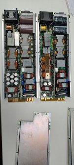
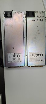
Rectifier Huawei R4850G2 48V 42~58V 3000w

Dominik H. What has happened to your 3000w charger? Your photos of your 0-90v charger was different from mine. Maybe I had a better version.
Mine died during charging. I opened it and had a look inside, but did not find any blown items. Did not measure or search what was defective.
Send it to someone who probably repaired it, but never got an answer what was wrong.

You can change the voltage up to 58V via CAN-BUS, you just need a USB-CAN converter and your Computer.
 
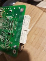
Hi. Can anyone help with the issue of connecting Smu02b to rg4850G2 directly. Maybe there is a basic sema of the Smu02b module with pinout contacts ? Or the chassis diagram where the Smu02b module is inserted ?
 
Is there a possibility to set an input current limit, like on the Vertiv or Megmeet rectifiers.

Megmeet uses nearly the same Can code as the Huawei.
Megmeet uses the same ID 10 81 80 FE for settings and for data request ID 10 81 40 FE like the Huawei.
Also turn output on and off via Can works on the Huawei Data 01 32 00 00 on , Data 01 32 00 01 off

Megmeet input current limit is Data 01 09 00 01 00 00 xx yy
 
Good afternoon.
Perhaps someone has an electrical circuit for R4850G1 and R4830G1. It is very necessary for repair. If anyone can help, I would greatly appreciate the help.
 
Is there a possibility to set an input current limit, like on the Vertiv or Megmeet rectifiers.

Megmeet uses nearly the same Can code as the Huawei.
Megmeet uses the same ID 10 81 80 FE for settings and for data request ID 10 81 40 FE like the Huawei.
Also turn output on and off via Can works on the Huawei Data 01 32 00 00 on , Data 01 32 00 01 off

Megmeet input current limit is Data 01 09 00 01 00 00 xx yy
Now I can answer my question myself.
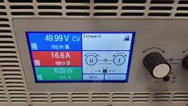
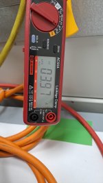
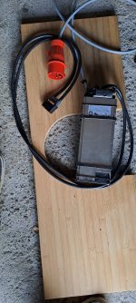
If you send 0X01 09 00 01 00 00 20 00 the AC input current gets limited to 8A if you send 01 09 00 01 00 00 10 00 it gets limited to 4A, as you can see on the pictures. The electronic load would draw 60A , but the rectifiers limits to the set input current.
Factor for multiplikation is 1024 and than it hast to be hex converted.
To turn the limit off send 01 09 00 00.
Measuremenst are taken with 230VAC line voltage.
IMG-20230731-WA0000.jpegIMG-20230731-WA0001.jpeg
 
Last edited:
I also tried to send voltage data to two parallel or/and serial connected units over one CAN channel.
The CAN is fully isolated from the output voltage, so you can use the rectifiers in serial arangement to get higher voltages, paralell for more current.

The rectifiers have to be adressed with ID 0x10 81 80 FE for the first rectifier and 0x10 82 80 FE for the second rectifier.
With this you can change the voltages of the rectifiers individualy.
Or just send ID 0x10 80 80 FE for changes to all connected rectifiers.

But sometimes they differ up to 0,3V in the output voltage, so it could be necessary to send each rectifier its own value, to be shure they share the load perfectly.
 
Last edited:
Did anyone successfully put two R4850G2 in series to reach +100Volts and cap the output current so it's working to a satisfactory degree and be robust enough?

I'm looking to reach ~109.2V but need to cap the current successfully since I don't have the AC Input Current to feed both of them at max (and would not want to to protect prolonge batteries life)

So far I don't have the R4850G2 yet but looking to get them if I hear from someone that has done it before (and can give pointers if needed), searched the forum with no luck.
The communication part is fine, just need confirmed that it would actually work and not cause issues with current/voltage sensing when ran in series.
 
Кто-нибудь успешно подключил два R4850G2 последовательно, чтобы достичь напряжения +100 В и ограничить выходной ток, чтобы он работал удовлетворительно и был достаточно надежным?
Да, их можно соединить последовательно. Подключите по 5-7 блоков, для зарядки машин. Регулятор тока и напряжения размещен только на одном блоке. При запуске сначала нужно включить блоки, а затем подключить аккумулятор.
 
Last edited:
Can also confirm that they work perfect in series. I have tried 2 in series and 4 in series.
 
Sounds great guys! That's enough for me to place the order :)
Do you do custom CAN messaging or use readily available products?

I'll take it as they have unique CAN addresses and they individually need to be addressed with the desired output current
 
Вы используете специальные CAN-сообщения или используете легкодоступные продукты?
Регулятор можно купить в Китае. Or use the native SMU02 controller.
 
Last edited:
Sounds great guys! That's enough for me to place the order :)
Do you do custom CAN messaging or use readily available products?

I'll take it as they have unique CAN addresses and they individually need to be addressed with the desired output current
I have programmed them before hooking them up in series.

But you can also adress them idependently, as I have written a few posts above.
Normally you only need to reduce the current of one rectifier when they are connected in series, the other can not output more current.
 
I have programmed them before hooking them up in series.

But you can also adress them idependently, as I have written a few posts above.
Normally you only need to reduce the current of one rectifier when they are connected in series, the other can not output more current.
Great, I will get them and try them out :) Thanks for your input

PS. So sorry I completely missed your post before my first one. It basically contained the answer I was asking for 🤦‍♂️
 
Last edited:
Here my new setup for charging my 21S100Ah Li-NMC scooter battery
Two Huawei RG4875G5 in series, controlled with a esp32 and can Chip, settings for voltage and current from the smartphone via Bluetooth for both of the psu.

Making up to 7,1kW charging power.
Maxing out two phases from a 16A 400V socket. Adjustable voltage range , input current/power and output current. (41,5-58,5Vx2) 83-117V 0-85A 0-8000W
Weight 4,5kg
20231017_175406.jpg

Screenshot_20231017_175055.jpg
 
Last edited:
Today I had a Huawei R4850G2 which does not respond to the input current limit, the rest of the settings do work.
I programmed 9 Huawei which all respond to the input current limt, so it seems to be a firmware or a version related problem.
The one on the right responds to the input current, the one on the left does not.
20231023_082728.jpg20231023_082715.jpg
 
Last edited:
To get slightly more charging current at low SOC levels and for charging with a petrol or diesel generatror.
 
Last edited:
In serial use I power the units before connecting them to the battery. If you try the other way they can die when the output capacitors charge not exactly in the same way/time.

In paralell use there is no need to power them up before connecting to the batterie, in real life they get always hot plugged, when they are inseret in their 19" racks. But i also do power mine before connection. I used a Zivan NG3 before and it has massive sparks during connection , when it was not powered up before.

The paralell units should have nearly the same voltage settings.
But I also testet different voltage settings. For example in a three phase 9kW setup for 16S Lifepo4 , phase 1 55,6V , phase 2 55,8V and phase 3 56V, so the BMS has a little more time to equalize the cells.

The inrush current is exactly the same 17A.
It only lasts a little longer when the rectifier is connected to the battery.
@dominik h
Do I understand that you have connected the power supply units in parallel and simultaneously supplied them with power from three different phases (i.e.: unit 1 to L1, unit 2 to L2, unit 3 to L3)? From other of your posts I understand that you did that and that you stated that no changes are needed to the PSUs other than CV to the same level. Is that correct?

I would like to have such a setup where I can adjust the current for each of these phases to charge one huge battery from solar power (already converted to AC) that would otherwise be fed back into the grid.

The amount of power that would be fed back into the grid differs per phase. I think this could be done by adjusting the current in the PSUs. I manage the power usage and can control the R4850 by ESP32, but I'm a bit scared the connect three of them on 3 different phases :/

Do you think that's possible with 3 R4850s?

Many thanks,
Bart
 
Last edited:
Yes they work from three different phases ( unit 1 L1-N , unit 2 L2-N , unit 3 L3-N , all connected to earth) and are connected to the same dc output in parallel to make 150A and more.
That is how they are powered in their original racks for telecom use.
You also can control the output current independently from one can bus control device or from an ESP32 with the change in the ID.

This also works in serial arrangements.
This is all the same for R4850G2 and R4875G1 and R4875G5.

I never had a R4850S on my workbench, I now they exist, but never had one.
 
Last edited:
When you insert the connector, pin "6" closes to the negative output, and the unit starts.
If you don't need it, you can cut off the track coming from the contact, in the place indicated by the arrow on my photo. And start the unit as before, closing contact 10 on a common wire. And you don't need to glue anything.

Do you know if it can be connected or disconnected with load applied? For example if my controller decides something is wrong or I hit the estop then does psu shut off safely without blowing itself up. I know it has short detection but I don't know how it operates, does it turn off the output when short is detected. In the can communication there a current limit setting, when the set current limit is reached does the voltage droop or does the output turn off completly. I want to make a failsafe deadman switch for my electronics, basically my microcontroller sends a clock signal to rc circuit that goes to a and gate and a not gate connected to the clock that also goes to a rc circuit and the other pin of the and gate. So the logic is that while the clock signal is being transmitted both capacitors will stay charged and enough voltage will go to the and gate to output logic 1 which then can be connected to some kind of relay, optocoupler, or logic isolator that connects the slot output detection to common. And so that whenever the micro controller needs to power the psu on or off it can do so by turning the clock signal on or off and if for some reason this pin on the micro controller gets stuck low or high or the microcontroller gets reset, loses power or gets fried then it theoretically should stop sending the clock pulse and only one pin of the and gate will get power.

When I measure the voltage from one of the output terminals to ground it reads like 50v and quickly drops to 0 linearly, I wonder if it's safe to ground the negative terminal? I'm not using it to charge batteries but for powering a motor inverter that also gets connected to a computer through usb meaning that it gets ground from the computer and if I were to connect the floating terminals from this psu something catastrophic might happen. I bought a usb isolator from ali for this and nylon standoffs for my electronics incase it is a danger. I don't want a ground loop anyways but if in case the negative terminal comes in contact with the ground what could happen?
 
Last edited:
If anybody is unhappy with the original fan control behavoir, I have a solution on github..
Github
Hello, the github solution you linked to doesnted exist. My r8475g1 will only draw a maximum of 1500w peak and will hover in the range of 400w most likely, I think the default fan speed at low load is too high and it's too loud for me so I want to reduce it or get a different fan that has a lower rpm limit and will simply spin slower at same pwm or voltage. Do you have a solution that doesn't involve having to buy a new fan?
 
The PSU does CC/CV . If the current gets to high the voltage drops, until the current is back in it´s limits.
The PSU can be hot plugged , but if the plug is already insert in the PSU and you connect the battery later, the output capacitors take really high current from the battery for a short time, which sometimes can blow the output fuse in the psu.

I have testesd a lot of things , but did not test what happens when you ground the output voltage, but I think nothing will happen.

I have a datasheet from a Huawai pin and can-code compatible rectifier, whichs claims insulation and voltage restitance 4000VDC input to output and 700VDC ouput to PE and 2000V input to PE, so it should be properly isolated, and the Huawei should be the same. The CAN from the Huawei is also opto islolated.
 
Back
Top