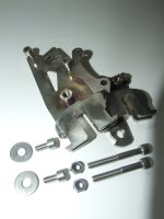
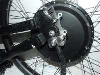
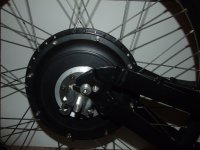
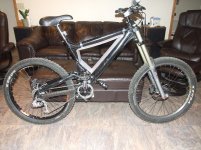
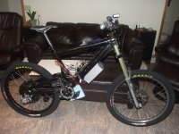
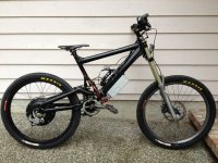
Scott's Giant DH Team Build 66 mph!

Must have forgotten to write on that controllers connectors. I usually label them with a sharpie.

3 pin female is throttle
3 pin male is 3 spd switch
2 pin female is ebrake
5 pin female is hall sensors
3 8 AWG wires with colored heat shrink tubing are phase, yellow is A green is B, blue is C
2 8 AWG wires coming from controller are power, red is batt positive, black is negative
1 thin red wire is the controller power wire, hook this to battery + to turn it on (up to 135V)
2 JST-SM connectors, small one is programming, large one is CA DP.

That should help.
 
zombiess said:
1 thin red wire is the controller power wire, hook this to battery + to turn it on (up to 135V)
That should help.

Thanks.

Is there any point to put a switch in between the red wire and the battery +?

Also my controller was not labeled at all so I do not know what the resistance of my sunt is. Would you happen to know what it is? I tried to measure it by testing the resistance between the CA plug shunt wires but I did not get any thing.
 
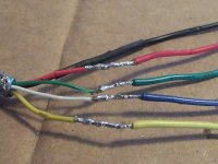
I made my motor hall wires >micro usb > micro usb > controller connection. It was pretty simple because most of the wires were the same color except instead of having blue it was white.
DSCF0946 usb to controller.JPG
View attachment 1


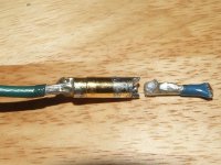
I cut the extra wire off from my motor phase wire to practice soldering bullets with my blow torch. The first 2 were easy, the 3rd was not practice and I could not get the wire tined (soaked with solder) so I added more heat and it worked.

The 4th one would not tin at all. So I let it cool then it seemed to kind of work the second time I tried. I had slid my practice female bullet on the male (real connecter on motor) while soldering so I would not get any solder on the male contact. But as I was soldering the wire on the male bullet my practice wire fell off. There was molten solder on the male side but I’m not sure if this should have happened or not.

Does this mean all of my soldering for the bullets is bad?

I forgot to get flux, is this my problem?
DSCF0957 fell off low res.jpg
 
Nope you don't have to use flux, the solder you are using already contain some flux?

You have to wait longer to make it sure the solder flows very well, that's is your problem.
 
MAGICPIE3FOCUSPOWER said:
Nope you don't have to use flux, the solder you are using already contain some flux?

You have to wait longer to make it sure the solder flows very well, that's is your problem.

I waited quite a while and it looked like the bottom of the wire started to turn black

yes I am using resin core solder 60/40. but the solder is 13 years old if that matters?
 
Nope it's still solder, but you can always buy new to try out :mrgreen:

Just heat the solder in the connector first, solder should flow now.
Then apply into the connector and heat again for flowing solder.

You can see when solder is flowing and when is getting cold (changing in color).
 
Are you saying to only fill the bullet with solder then? Because I thought that you needed to tin the wire also because it is so large. Also these 5.5 mm bullets only have 1/2 of a cup to fill with solder.
 
Yup to have to fill it first ofcourse not filling to the top! :mrgreen:

But it's no problem to fill it to the top, it will just dripping out when wire is applied.
And it's just more work to remove the solder around the connector.

Filling solder in the connector is easier, because this way you create a better flow when heating/soldering.
And less chance to damage your wires when heating.
Don't forget to apply some solder first on the wires before soldering to the connector.
 
MAGICPIE3FOCUSPOWER said:
Don't forget to apply some solder first on the wires before soldering to the connector.

By some do you mean a little on the end of the wire or completely filling the wire with solder until it is about to drip?
 
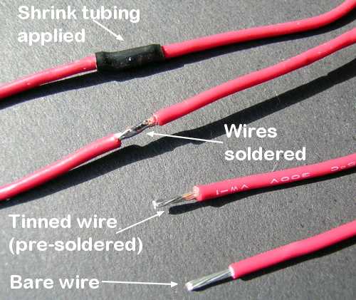
I mean like when you you are buying new wires they are most of time pre-soldered.
Wire%20splice.solderikng.jpg


And when you have applied the wire to the connector and there is not enough solder, you can always apply some more :mrgreen:
 
I figured out my soldering problem, for some reason the blow torch will not work to tin the wire, but my soldering Iron works great for that. The blow torch is very helpful for heating up the bullet connectors to melt solder in them.

I already knew that turnigy batteries were better than zippys but I was going to go with zippys because I would save money and it would be easier to mount them because of their shorter and fatter size vs. the turnigy batteries. Although after watching GCinDC’s video with the cell voltages being recorded on the adaptive mini-e it convinced me that I needed to make the turnigy batteries work in my set up.

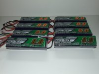
8x Turnigy 6s 8000mAh batteries:
DSCF1017batteries low res.jpg


I also received my Kiwi drop out adaptors:
kiwi drop out adaptors low res.jpg

I am in the process of building my polycarbonate battery box and have done some strength testing that I will make a video of and post later when I have time.
 
litespeed said:
Build looks excellent!

Tom
Thanks

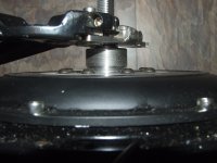
Today I was able to grind down the drop out adaptors so they would fit in my bike frame. I had to file/grind quite a bit off of the left corner (in this picture) so it would fit on the swing arm. I had to grind for just 10 seconds on the drop out part so the motor axle would fit, it is very sung.
DSCF1030motor mounted low res.jpg

The wheel may need to be dished a little bit to the left. With a tire on the tire will only have 3mm of clearance on the right side.
DSCF1020wheel space low res.jpg

unfortunately it will be a week untill I get my throttle and CAv3 but when I get them every thing should be ready to go!
 
MAGICPIE3FOCUSPOWER said:
Thanks for your nice pictures!
Also do you have more pictures of freewheel side?

Your bike is not nice, but super NICE :mrgreen:

My bike has so many paint chips but the second bike the 2005 one is in really good condition so the swing arm will look nice.

Yes I take lots of pictures. I don't have the freewheel washer on there yet I was just doing a test fit.

DSCF1031motor mounted low res.jpg
DSCF1035freewheel side low res.jpg
Yes I know it is sad my motor got dust on it... this camera takes too good of pictures.
 
last night I got my larger swing arm put on the bike and I installed the cromotor on it. it took 4 hours and it was late at night so I carefully rolled my bike 5 ft to stand it up so it would not tip over. This morning I carefully rolled my bike back to my work area and flipped it upside down just to see that my disk brake sliced through the insulation on my blue and green phase wires and copper is showing now :( . I will try to get some electrical tap in there but I might have to take the cover off the motor to get to the wire.

EDIT: The disk brake only sliced through the white heat insulation but making the wires bend over the bolt that keeps the axle for coming out of the kiwi drop out adaptors made the wires crack. All 3 phase wires have the insulation cracked at the bend where they where bent over the bolt.
 
Chalz said:
looking forward to seeing how your going to get those batteries in the frame. Any pics yet?

Your battery box looks very nice and strong.

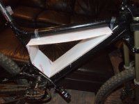
I am making it out of polycarbonate I have the outer shell done now I just need to get side panels cut. It is welded/bonded together by welding cement that softens the plastic and makes both pieces one piece after 24-48 hours.
DSCF0958 low res.jpg

DSCF0959 low res.jpg
 
......Im watching guys(lurk,lurk)

il be posting too soon...just gotta get my stuff together and figure out how to reduce my photo file size.....its never been a strongpoint.

very nice work.
realy helpful to learn from.
thanks
 
My bike kinda works. The motor will spin normally with the CA unplugged only

On Sunday I had every thing hooked up but nothing happened when I pressed on the throttle. First I was using the original XPD to program my controller. Then I tried out zombies edited version witch I got working and will explain how to install that later. With using the zombies program "EBxx V2" I was able to get a sound with the motor, then I unplugged my CA and the wheel spun around 15 mph (guessing) and made an odd sound like it was trying to go faster. Then I thought I would try to change the setting I did not know what to set to: indicate mode from 1:comm GND to 0:Comm VCC. With it set to "0:Comm VCC" my motor spins very slow with the CA plugged in, with the CA unplugged it spins at around 25 mph (guessing) smoothly .

these tests are being done freewheeling (spinning in the air) the rear wheel and with 12s lipo (50v).

Zombies had a similar problem I found but his CAsaid he was pulling 24kw however mine says i'm pulling 1 watt. I know my CA shunt wires are connected to the controller because I used my CA to calibrate my shunt

edit: Also just more information with my CA plugged in it draws 0-1 watts. If I spin my wheel backwards it instantly stops if I press on the throttle. If I press on the throttle and spin the wheel back wards my CA says 10 watts are being pulled. (I cant turn the wheel backwards any harder with my hand)
So because of this I believe this is a CA setting problem but it could also be a controller programming problem too.
when I press on the throttle and go into the CA settings for throttle it goes up from 0.00v to 0.01v and the % stays at 00%
If I make the throttle go through the CA and press on the throttle it goes from 0.91v to 4.19v and the % shows 1% to 99%
 
ridethelightning said:
......Im watching guys(lurk,lurk)

il be posting too soon...just gotta get my stuff together and figure out how to reduce my photo file size.....its never been a strongpoint.

very nice work.
realy helpful to learn from.
thanks
Thanks.

I just open my photo up with paint and click save as: "original name/number low res" then I use the re size button and put in 30% (or what ever size smaller you need) and click ok. you need make it small enough until it is under 512kb.

to open up your photo in paint you go to your photo and right click open with > paint
 
I had my bike running before I started my first quarter of college which was my goal!
I will get some better pictures tomorrow when it “should” be dry and sunny.
DSCF0187 bike low res.jpg

I have done a lot to my bike since I last posted.
Bike:
- Trued front rim. When my bike came it had 5 loose spokes on each wheel (not motor) and so I just tightened the loose ones to go DHing, now the bike is so stable with the rim trued I can easily let go of the bars and attempt to warm up my frozen hands.
- Maxxis Hookworms front and rear.
Motor:
- Replaced/ shortened phase wires since the disk cut them.
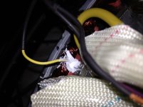
- Added temp sensor to windings using Arctic Alumina.
Controller:
- A fet went out but zombiess has great customer service and fixed it for me.
- A few days ago Zombiess discovered a problem that the green phase wire needed to be moved to prevent blowing another fet. http://endless-sphere.com/forums/viewtopic.php?f=2&t=54891
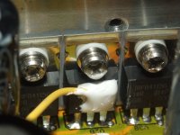
- I moved the green phase wire. And added a temp sensor to a high side fet body while I had the controller open. I also used Arctic Alumina to epoxy the temp sensor down.

Unfortunately my hall sensors are at the very bottom of my motor so I am worried about them shorting out due to water.


Temp sensor in motor.
temp sensor in motor low res.jpg

Temp sensor in controller.
DSCF0199 temp sensor on fet low res.jpg

Extra pavers can make a useful bike stand while free wheel testing. This may only work with Giant DH Teams/ Comps. A motorcycle stand may also work Teams/comps.
View attachment 1

I will get some videos up on here. I went for a ride yesterday but only made it 2 laps around my neighborhood, before giving up due to getting soaked with water (typical Seattle rain) and not being able to see.
 
Here is a better picture:
Bike mid done out side of house low res.jpg

To day I added a 3rd battery for 18s, ~70 volts. The controller is set to 48 battery amps. I hit 45 mph twice on my way to my old school, and the motor only pulled ~40 amps while going 45 mph. When riding up the 4-6% grade hill (pretty steep) my old school sits on I was able to do 35 and could hit 40 in the lesser steep parts. It was awesome to be able to do the speed limit up that hill vs. going 20 mph (35 mph is the speed limit) peddling hard as I could and breathing in tons of exhaust from the school traffic. I have some video of today's ride but windows live movie maker is a piece of junk. I’ll make a video tomorrow.

After today's ride I can say this bike/project was/is definitely worth it!

Now, to get to 24s and up the current some.
 
Back
Top