Solar Power Cruiser - Terratrike

dogman said:
I'd love to be able to ride into the sticks, then just sit in a camp charging enough to get back to plugs. The sides of my panniers are about 30" x 16" So two panels about that size would carry great on my longtail. I'm thinking more in terms of charge stationary though.

If you aren't in a hurry, stationary charging sounds like a fine idea. And if you ARE in a hurry, what are you doing on a bike out in the sticks. Before I hooked up more battery, I was perfectly happy with the idea of going 20 miles, stopping for a three hour rest and lunch and then riding 20 more miles.

Having two panels is a good idea. I am learning the hard way that the up-converter and batteries are not a great match to a single 12V panel. With a max power point at 17.7V and 5.7 A, the panel is looking for a load around 3.1 ohms. On my bike, when the battery is deeply discharged, the panel is running at 12V and 6A -- which means that it is seeing a roughly 2 ohm load and I am not getting full power out of the panel. What I get into the battery at that point is typically around 1.6A at 38V for a power of 60W into the battery and an up-converter efficiency of ~85%. As the battery gets full, I get better performance. With two 100W panels in series, the max power point is 35.4 volts and 5.7A which is a good starting point. Hell, the open circuit voltage is 21.7 per panel or 43.4 volts. I could ALMOST use the two panels without any DC-to-DC converter at all. OK, I just decided to get another panel. Busybee's solution is just too cute to ignore and is a much better solution electrically than my single panel. Besides, the simulator @ ebikes.ca says I can go 18mph on level ground with only 150W. So, through the midday hours I would just about break even as I ride !!
 
dogman said:
Two panels at burning man sounds perfect. No high speed riding so the wind drag hardly matters. But the shade as you ride could be priceless.

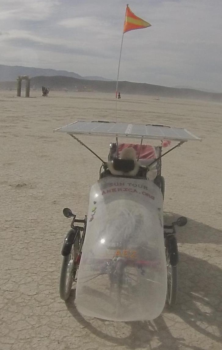
Panel frame is a half inch thick and underway is always horizontal. There were high winds at Burning Man and extra windage from panels was not noticeable. The fairing more than cancels it out. A string of LED lights around the panels makes finding the trike at night in a sea of bikes easy. Lots of bike carrying LEDs, but not panels to put them on. I'm thinking to add an Arizona Whip or make the equivalent if only for added safety.

The fairing helps keep the rain off, but in Arizona that is a rare issue. Far more useful, the fairing can be covered with Spandex for better safety (neon for being seen) and to provide more shade. When it is 110 in the shade, riding a recumbent is like laying flat out on the beach to catch the sun. Riding made-in-the-shade with a mister bottle and a 2 quart thermos full of ice water hanging behind the seat with a tube as long straw works wonders.

GOPR0049.jpg


As for speed, I support the EU speed limit of 15.5 mph for ebikes that want to be considered bikes and not e-motorcycles, which will get them banned from using bicycle transportation infrastructure as is happening. Ebikes are banned from using bicycle paths where I live, Tucson. Better to go fast enough than get banned. Although my motor is "off-road" and all speed limiting can be turned off, I've set it to 25 km/h just because 15 mph is fast enough. At Burning Man 5 mph was fast enough, at times far too fast on the pedestrian filled streets, and on the open deep playa 12 mph was good as 15 mph seemed too fast. To paraphrase Shakespeare, 'nothing is either fast or slow, but thinking makes it so.'
 
icerider said:
Having two panels is a good idea. I am learning the hard way that the up-converter and batteries are not a great match to a single 12V panel. With a max power point at 17.7V and 5.7 A, the panel is looking for a load around 3.1 ohms. On my bike, when the battery is deeply discharged, the panel is running at 12V and 6A -- which means that it is seeing a roughly 2 ohm load and I am not getting full power out of the panel. What I get into the battery at that point is typically around 1.6A at 38V for a power of 60W into the battery and an up-converter efficiency of ~85%. As the battery gets full, I get better performance. With two 100W panels in series, the max power point is 35.4 volts and 5.7A which is a good starting point. Hell, the open circuit voltage is 21.7 per panel or 43.4 volts. I could ALMOST use the two panels without any DC-to-DC converter at all. OK, I just decided to get another panel. Busybee's solution is just too cute to ignore and is a much better solution electrically than my single panel. Besides, the simulator @ ebikes.ca says I can go 18mph on level ground with only 150W. So, through the midday hours I would just about break even as I ride !!

That's why I got the converter with the current limiting, the ability to turn down the charging current to the battery, that will keep the panel from working into too low a load impedance at low battery.
 
Debatable that 5 mph would be too fast to really appreciate the art at bm. I've never been to it though, I blow my annual vacation on the Albuquerque balloon fiesta every year. Another gigantic week long party.

I ride faster when just going for some groceries, but 15 mph on multi use paths is about right. They put the signs up all over Las Cruces too, but I just ride like a gentleman and ignore them.

On a long tour, 15 mph is perfect for me. The whole idea for me is to SEE this road I drove thousands of times, for the first time. At 25 mph, all I'm seeing is the next piece of glass I need to dodge.

I'm thinking maybe for my needs to carry it, two of these might work. https://www.renogy-store.com/50watts-bendable-panel-p/rng-50db.htm

Better though, if they were more like 18x30 than 25 x25. Starting out closer to pack voltage does make sense to me too. Might match well for 36v. 50w is not much, but it's about equal to what I pedal. Cruising at 200w, using only 100w from battery would help a lot.
 
dogman said:
Better though, if they were more like 18x30 than 25 x25. Starting out closer to pack voltage does make sense to me too. Might match well for 36v. 50w is not much, but it's about equal to what I pedal. Cruising at 200w, using only 100w from battery would help a lot.

I love the balloon festival too. Last year I was unexpectedly invited to fly with Crispin Williams who is a pilot and sales rep for Kubicek balloons. It was my first balloon flight and the balloon was a racing model. WOW, that racing model can change altitude FAST !!

Anyway, I think the 2x50W config would suit you well. The area of the "flexible" 50W from Renogy is pretty minimal. The cells are 20% efficient which is near the current commercial limit. That would make the alternate size more like 18x38 to get the 50W. If you are carrying them so that their center of gravity is reasonably low, then you could also look at traditional glass-faced models which would give you more freedom in shape just because there are more vendors to look at. Total weight would be 18-20 lbs.

Yes, I found that cruising slowly and smoothly on relatively flat rolling terrain, even 70W made a HUGE difference in battery life. The 70W is an estimate. Even with near-full battery, I am not getting the full 100W because of the impedance/voltage mismatch. 2x50W solves that problem. If the sun were directly overhead, you should get pretty much the full 100W and the converter should run above 90% efficiency with that small a mismatch (assuming 36V battery). As the voltage mismatch gets worse, so does converter efficiency, but mine is ALWAYS above 85%. I have GOT to get a watt meter
 
OK, my second panel should arrive today.

I plan to copy Busybee's arrangement with 1/2 inch Al tubing.

Then we'll see whether I need the DC-to-DC converter at all. It depends on what my open circuit voltages are, it is going to be a near thing in any case. I will check components on the converter I have to see if I dare overvolt it by 20% on the input side. I'm not too worried about max power since it has superb cooling, but the input volts may be a problem.

Running without the converter is attractive, if for no other reason, because the installation would be "cleaner" looking. I can certainly put a voltmeter on the panel output (battery input) and a switch to turn off the recharging when it gets above 41.xxx volts. While I am riding that shouldn't be a problem. If nothing else, I can ride a couple of miles on throttle to get the battery down to <41 volts and then just let the bike run pretty much off the panels.

If I really need a converter and my current one won't work, then I can go ahead and buy the 600W converter.
 
Bear in mind that the input voltage flows right through a boost converter, there is no way of turning the output voltage down below the input voltage so if it's too high for your batteries in full sun it still will be with the converter in the circuit.

You could put a big diode or two in the output circuit to knock a few volts off it though.
 
If open circuit voltage is greater than top of charge pack voltage, then use a different type of converter that steps it down and won't flow above the set voltage. Another alternative is to arrange panels so the open circuit voltage is a couple of volts above top of charge voltage, ie no more than trickle charge power available from the panels between the 2 voltages anyway, and then use a simple voltage cutoff circuit to protect your battery. The panels I use have an open circuit of 21V and I use 5 in series for my pack top of charge of 83V. Above 80V-81V, the current from the panels starts falling off, so it results in quite a good approximation of CC-CV, and then I have the pack protected by the voltage cutoff circuit at the top.
 
Jonathan in Hiram said:
Bear in mind that the input voltage flows right through a boost converter, there is no way of turning the output voltage down below the input voltage so if it's too high for your batteries in full sun it still will be with the converter in the circuit.

You could put a big diode or two in the output circuit to knock a few volts off it though.

You are quite right that many boost supplies will not regulate down. In particular, the one I am using does not appear to be able to do so. On the other hand, it's design point is 150w with no more than 30V input. The fancier 600W module will regulate up or down (or says it will). My open circuit voltage is published at 21.7V per panel for a potential total of 43.4 which is above the 42V max charge on my 10s6p LiMn battery and above the 42 max volts for the 10s 5Ah LiPo pack in parallel with it. It is possible that my panels will not quite live up to their specs and the Voc will be acceptable as-is. My recollection is that the measured Voc on the first panel was something like 20.9V so there is some hope. How's that for irony that I am hoping that my panels are just "a little low". In any case, there won't be very much current flow with only 1.4 volts driving it, so any time I am using the bike it will not be a problem.

I had thought about using 3 or 4 diode drops to cut the Voc down to something below 42V, and that is probably a workable path forward if I need it..
 
John in CR said:
The panels I use have an open circuit of 21V and I use 5 in series for my pack top of charge of 83V. Above 80V-81V, the current from the panels starts falling off, so it results in quite a good approximation of CC-CV, and then I have the pack protected by the voltage cutoff circuit at the top.

I am hoping that it's 4 panels for a Voc of ~81V.

I am REALLY hoping my Voc for the panels in series will be < 41.8V under any reasonable Arizona solar illumination. If not, I can deal, but it would be simpler not to have to.

If you don't mind my asking, what are you using for an over-volt protection circuit ?

My voltages are so close to being "right" that I will be sorely tempted to just put a cheap little voltmeter and a switch on the system, or, as discussed above, 3 or 4 diodes for a 1.5-2 V drop.

With a silicon forward resistance of .1 ohm per diode at 5A, the total dissipation in a 4 diode string could be as high as 8-12 W which seems like a high price to pay for a 2V voltage drop. On the other hand, silicon diodes are CHEAP. Looks like $1 each on Amazon.
 
It never fails, buy a solar panel and Sol goes away and a hurricane shows up. Not much of a hurricane either.

Anyway, second panel installed at least in a prototype way.

All wired up. Wired direct with a blocking diode to prevent backstreaming.

We'll see what the open circuit voltage is next time the sun shines. Hoping it is just below 42V -- should be close.

So what can I do with 200W ? http://www.ebikes.ca/tools/simulator.html says that a fat man on a recumbent can go 18.4mph on level ground with a Bionx PL350 @ 159W.

Vielleicht scheint morgen die Sonne wieder.

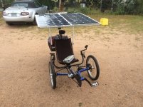
2panel_1_small.JPG

Update 9/18/14 AM:

Nein, die Sonne scheint nicht weider. 1.34 inches of rain and counting -- right now it is just misting, but too wet for a ride, and still no sun at all.

Did manage to get out for a few minutes yesterday late afternoon. It was right before the remnants of Hurricane Odile arrived. Wind was pretty high 25mph gusting to 35 or so. The panels were simply not affected by the wind. Since they are horizontal there just isn't much for the wind to grab onto, but there was virtually NO perceptible influence from the gusts. The added weight from the frame and second panel is not too bad, but it is larger and has a higher moment of inertia in the yaw (rotation right and left) axis. Bumps make it rotate slightly right and left and I can feel that input to the bike. I added two temporary "struts" from the solar panel frame to the rear rack. It is just baling twine tied so that it is in tension and prevents the rotation. That should reduce the tendency to wobble left and right.

I am still using the PVC supports that I used for the single panel and may end up replacing them with something stiffer. The effect on the bike is not actually very great, but the wobble can be felt and is an invitation to "pilot induced oscillation" if I try to correct for it. The frame of the Cruiser is CroMoly and pretty flexible in the "twist" direction, which doesn't help. Still, it seems quite rideable as is and there is a LOT less "squeak" from the PVC. There are a number of possible support options left to try if this arrangement is too loose for my taste. Can't wait for full sun.
 
OK, The 2-panel version is, for the moment, finished.

After determining that the open circuit voltage was unlikely to exceed 42 volts I decided to re-use the original DROK DC-to-DC upconverter. It's published limit for power is 120W, but it is VERY well cooled and does not get particularly warm in-run. It's published upper limit for input is 32V, but it is working fine for the moment, we'll see how it holds up. When the (parallel) panel voltage rises above 34 volts, we are in the final stages of the charge and current flow is low so total power is low. The voltage limit is likely based on the caps, and if they survived their first exposure, they are likely to continue to do so. The choice to stick with the smaller DC-to-DC converter left the electronic package unchanged and MUCH smaller than it would be with the 600W converter. It also left the 600W converter available for another project.

The only real changes are the change from a single panel to two panels wired in series. The power output has roughly doubled as expected and the voltage match -- input to output is better so the converter efficiency is improved. The efficiency improvement is sufficient that it actually seems the converter runs cooler now than it did with the single panel.

The only problem was how to run the 12v cooling fan. The original cooling fan could run on a voltage between 10V (loaded panel) and 19-20V (unloaded panel). This worked very nicely indeed, and matched the panel pretty well, but was not a good match to the cooling needs. When the panel was loaded, the voltage was low and the cooling was limited at the very time that cooling was needed most. When the battery was full, the panel was unloaded and the fan ran GREAT, but little cooling was required. SO, how to manage the fan. The straightforward solution is a second small DC-DC converter to convert battery voltage to 12V or so for cooling. But, this complicated the electronics and made another circuit that needed to be protected with a diode to be sure that if it died it could not short out the battery (remember that half the battery pack is RC LIPO which is pretty allergic to shorts.

A quick glance around the garage produced a small 7x7 inch 12V solar panel that originally was part of a solar powered motion controlled light. A quick touch of solder and the cooling fan now has its own panel entirely separate from the main solar system. Bright sun...high fan...no sun...no fan, and no drain on the battery. Actually, the little panel is roughly 6W so it and a small battery would happily run the rear light system at some point in the future.

Anyway, now looking for a cool day with good sun to get out and REALLY exercise the bike. First planned tour is just 36 miles total, but may not happen for a couple of weeks since I am going to Albuquerque for the balloon festival. I'll report when I have good data for charging characteristics of the 2-panel system. I would be insanely happy with 150 W peak charging with the bike tipped to the sun. I also need to rig a way to monitor the panels performance during a ride with mid-level battery. Under load, with 50% charge, the battery voltage (at the charging system) should drop top ~37 volts and allow the panel system to provide whatever it can without hitting the 42V high-volt limit of the DC-DC converter. I have a cheapie volt/amp meter that I can wire in, but what I really need is a WATTSUP or cycle analyst.

Anyway, more to follow. One experiment planned for later is to determine whether the performance is noticeably different with the panels wired in series or parallel. The current configuration is in series which provides a better voltage match panel-->charging system. In parallel would cause a larger voltage difference but would LOWER the effective impedance of the panels which might allow more power to be drawn from the panels (although the losses in the converter will go up because of the greater voltage mismatch). An interesting question for later.

PS, if somebody knows how to calculate that impedance-matching problem panel-->application, I would appreciate a detailed lesson.

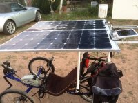
2panel2.JPG
 
Icerider,

Very cool design and thread. Good job.

You caught my eye because I was thinking about solar-charge-supplementing as a curved cover over an extracycle.??

I did an intial PV design, but I wasnt sure the interaction between the panel, upconverter and input into the battery via a schottky. You did the experiement for me and showed the panel got loaded doen to 12v. I want a robust design, so I was thinking of a 200W upconverter with a 100W panel.

The LiMn are rugged and self balance , true? Just heavier? Have you had any battery cell problems going right up to 42v?

Again, very nice project and cudos for the triple win: free charge, range extention, shade.
 
Bike_on said:
Icerider,

... I want a robust design, so I was thinking of a 200W upconverter with a 100W panel.

The LiMn are rugged and self balance , true? Just heavier? Have you had any battery cell problems going right up to 42v?

Thank you for the compliments.

With a single 100W panel you are unlikely to need more than 100W converter, but 200W will be fine and if, like me, you decide to add a second panel you will not wind up overdriving your DC-DC upconverter.

Yes, the LiMn are supposed to be relatively self balancing and tolerant chemistry. Bionx clearly thought so when they were building the I2C (pre-2009) systems because neither of my Bionx batteries had any real BMS. There are only two wires to the battery, positive and negative. No cell monitor or balance leads at all. There are thermisters for temp monitoring during charge with the Bionx charger.

My current battery is actually two separate packs: the Bionx 9.6 Ah 10s6p LiMn battery (current capacity ~8Ah) and a 5Ah 10s RC LIPO pack wired in parallel with the Bionx battery. The LiMn Bionx battery is an I2C battery and is almost certainly no newer than 2011 manufacture so the 8Ah capacity remaining is spectacular. I never actually charge to 42V. The upconverter is set to 42V open circuit but in practice, the batteries are never charged above 41.7V. The internal resistance of the batteries is low so the charging voltage is never very far above battery voltage. Studying just what that relationship is is on my todo list, but I think the difference is never more than 0.7V or so and probably lower than that.

The best charging performance I have seen yet was pushing 4A at 37 volts (148W) at the output of the DC-DC up converter. This was with the panel tipped toward the sun at about noon. The panel was not perfectly perpendicular to the sun, but it was pretty close. The battery had less than 20% charge at that point. Assuming a 90% efficiency, this is 6A at 27.5V at the panel. It shows the panels are loaded beyond their max-power point and are running below Vmpp and at roughly Isc. It also means that my best charge rate is ~1/3 C which is pretty reasonable. Maybe a little high for the LiMn and pretty gentle for the RC LiPo cells. I doubt that I will ever see that charge rate with the bike sitting flat or moving. At this charge rate, the system charges in 3-4 hours if I manually track the sun, adjusting the pointing of the panel every hour or so. Neither the Bionx battery nor the LiPo pack warm up at all during charge as near as I can tell.

I have no way to gauge the long term effect on the LiMn batteries. I check the balance of the RC LiPo pack every couple of days and so far they are staying virtually perfectly balanced. They probably have ~40 charges on them so far and their capacity is still reported to be very slightly greater than their 5Ah rating which is no measurable change since delivery.

I typically run the batteries (in parallel) between 41.7V full charge and 36V (shut down the electric assist) which is pretty conservative but is also 90% discharge. The charge curves of LiMn and the RC LiPo are VERY similar which prevents much cross-charging as the load varies.

I'll update as I get more experience with the system.
 
I've been working on my solar powered recumbent, SoLong.. :D

The 600W booster does a fair to decent job of charging the 12s pack from the single "12V" panel, I get 4 to 5 miles of 21mph cruising charge from each hour of full sun (60-75 Wh), it's too hilly here to ride much on just the panel watts alone.

So far I have the panel mounted on an old trailer I keep around for shopping and when at home I put it on one of my big photo tripods so I can aim it and move it around easily.

So_Long1.jpg


So_Long2.jpg


So_Long3.jpg


So_Long4.jpg


So_Long5.jpg


Oh, and here's my early prototype of an Arduino based MPPT controller that I'm planning on interfacing to the 600W booster by unsoldering the gate lead of the MOSFET and controlling it with the Arduino through an optoisolator. You'll note that I have Battery Amps and Volts numbers transposed in this picture, figuring out the interface to the LCD has been the biggest pain so far. The smaller board to the right is a 20A current sensor and the other stuff is the voltage dropping network for the solar panel input.

So_Long6.jpg
 
icerider
thank you for post
It must be exciting to see this battery charged from just being in the sun,
what a wonderful rolling proof that the biggest source of energy on this planet /solar/ can be put to use with success.
Also, notice price of panels goes down while efficiency up with every year passing.
 
Jonathan in Hiram said:
The 600W booster does a fair to decent job of charging the 12s pack from the single "12V" panel, I get 4 to 5 miles of 21mph cruising charge from each hour of full sun (60-75 Wh), it's too hilly here to ride much on just the panel watts alone.

...

Oh, and here's my early prototype of an Arduino based MPPT controller that I'm planning on interfacing to the 600W booster by unsoldering the gate lead of the MOSFET and controlling it with the Arduino through an optoisolator. You'll note that I have Battery Amps and Volts numbers transposed in this picture, figuring out the interface to the LCD has been the biggest pain so far. The smaller board to the right is a 20A current sensor and the other stuff is the voltage dropping network for the solar panel input.

Good to know your results with the 600W booster are pretty much the same as I am getting with my smaller DC-DC booster. I have the 600W on the shelf but elected not to install it right now. I am overdriving my smaller booster pretty badly at the top end of the charge and it may give up the gosling at some point. Knowing the 600W works well means I can worry a little less about that happening.

That Arduino based MPPT controller is one CUTE idea. I have been puzzling through how to get the panel(s) back closer to their max power point and wondering whether it makes any real difference or not. I will follow your development with interest.

I am also pea green with envy at your instrumentation. I am pretty sick of having to make and break connections to make measurements and I am tired of buying 10A fuses for my multimeter because I can't remember to change functions when I go from current measurement back to trying to measure voltage --- wow, that can be one BIG spark, and with the RC LiPos in the loop it is one dumb and dangerous mistake to make -- thank god for 10A fuses.

Right now I am torn between concentrating on measurements of the system and getting out to get some real practical experience just RIDING it. On my daily 12-14 mile route, it does GREAT. I am NOWHERE near the battery limit, but those rides are in the dark or early morning twilight so the solar panels are just along for the ride. When I get home just after sunrise, I set it up to charge by putting the rear wheel up on a plastic bucket pointed to where the sun will be in 2 hours and it charges fully before noon. Then it just sits in the sun until I get home.

I think I really just need to get out and ride from 10am to 2pm and see what it does in "real world" use. I have a 30+ mile ride to Kartchner Caverns and back all mapped out. It is a good route with wide shoulders and only 8 miles total on the I-10 shoulder (which is not NEARLY as scary as I expected). But ... I am a little reluctant to set out on that ride without a local "prove-in" of roughly the same length. With a cruise speed of 14-15 mph average, that will take a couple of LONG hours and it needs to be near midday to get a real feel for how the bike is working. Midday is still pretty HOT at ~90 degrees so that may not be the most pleasant ride I have ever made. On the other hand, I am by definition "in the shade" with a good 15 mph breeze to stay cool.

I did have some experience with the single panel setup riding near midday and it was MUCH harder to run the battery empty than without the panel. On the Kartchner round trip with the single panel (7-10am) I used only a net 3Ah out of my battery. The back half of the ride was slightly downhill on average and the battery was (net) charging !!! for that half of the ride. With 2 panels near midday I should be able to get 30 miles without really denting the battery at all. Tomorrow will be my first real opportunity in three weeks to get out and ride at midday ... I'll report how that goes assuming I make it.

Handling: A final note now that I have 100+ miles with the two panels mounted. The handling with the two panel layout is not noticeably different than the single panel, except... The bike is wider now and the width is the panel, not the front wheel stance. I have to be CAREFUL going through my electric gate to look at where the PANEL is with respect to the gate (I was used to looking at the front wheel). The bike is also more subject to oscillation in the roll axis, there is simply more weight up in the panel and it is easier to get it swinging back and forth left to right and because it is heavier than the single panel it has more effect of the relatively flexible CroMoly-framed Cruiser. It is irrelevant at normal riding speeds (15-17 mph on level ground), but on a long downhill (22-25 mph) I have to be more careful to watch my technique and damp out any oscillation. This is not a big deal but it does take some getting used to. It took most of that 100 miles of experience to get back to feeling secure at 25 mph.
 
miro13car said:
icerider
thank you for post
It must be exciting to see this battery charged from just being in the sun,
what a wonderful rolling proof that the biggest source of energy on this planet /solar/ can be put to use with success.
Also, notice price of panels goes down while efficiency up with every year passing.


Yes, the next few years is going to be interesting.

The utilities are getting worried and looking for new "fees" for grid tied solar systems. SOME of that is fair. Grid tied systems do use the grid at night and with net metering, the utility is basically forced to buy the excess power produced by the panels during the day at the "retail" rate. It will be interesting to see which utilities manage to figure this one out and make peace with their solar-enabled customers and which utilities manage to make their solar-enabled customers "cut the wire". The cable folks are already learning that we can do without their dubious services, subscriber numbers are down across the board for every cable system and those idiots just keep raising their prices to make up the difference. That way lies bankruptcy.

There are a lot of morons in the business world who have been taught to think that their stockholders come first. CUSTOMERS come first. Without them there IS no company and there ARE no stockholders. History is littered with the lifeless bodies of companies that forgot that simple rule, and you can use their stock certificates for wall paper or kindling. This is a particularly hard lesson for utility-like companies to learn. They are so used to the "we don't care, we don't have to, we're the phone company" approach that they learn ONLY from financial pain.

If you are doing a good job and delighting your customers with products that they want or need and see as high value, profits and growth will follow. If your business plan is to charge ever higher prices for products your customers can elect to do without you are going to discover what the phrase "elastic demand" means. Discover that unpleasant fact in an environment where you are stuck with high fixed operating costs and your company is dead meat. The utilities are in EXACTLY that environment right NOW. Solar is getting cheaper by the minute and for those of us luck enough to have the room, solar makes more and more sense (with the current rules). Once I have the solar capacity, the only value of the grid is its "storage" capability. Net metering under-values that "storage" capability. Net metering is a safe approach only so long as additional solar generation allows the utilities to avoid building additional peak generating and transmission capacity. The utility saves money and the solar-enabled customer saves money and the system goes on working. But when solar gets cheap enough that a bigger fraction of the customers begin to go solar, the utility begins to idle generating capacity. At that point, the utility is not saving that much money since they still own the idle generating capacity and are still paying the loan they took out to build it. Their operating costs don't drop much but they lose customers. NOW the utility begins to have to charge for the grid's "storage" capability, and hence the "solar fees".

When this happens, the solar-enabled customer has a bill to look at and evaluate against the cost of owning their own storage or night-time generating capability. One of my solar-enabled neighbors has already "cut the wire" and I can hear his generator running at night -- every night. Now, take this environment and drop a cheap storage solution into it and the utilities get HURT. That cheap storage solution does not exist yet, but the EV market is driving a LOT of related research and manufacturing capability which in turn creates economies of scale, reducing the cost of storage capacity. If I didn't work, had an Electric car and a smaller and better insulated house, I would be asking myself the following question: "Can I reduce my late afternoon and night-time electric usage to the point that I can solar generate during the day storing the midday excess in my car battery, run my errands in the morning or early afternoon and then run off the electric car battery at night?" I think the answer right now is either no, or that the wear-and-tear on the car battery would require early replacement and cost enough that it is uneconomical... ask again in 5 years.

If the topic of solar and the utility companies is of interest to you, you might try the links below as a starter. They are easy Google results.
I have read them all, but have not made any serious attempt to provide a "spectrum of opinions". The utility position that net metering results in non solar users subsidizing solar users is at least partially true. The question is how we will address that issue.

http://www.bloomberg.com/news/2013-11-15/arizona-regulators-impose-power-grid-fees-for-solar-roofs.html
http://thinkprogress.org/climate/2014/09/14/3567244/utility-fees-end-wisconsin-solar/
http://www.bloomberg.com/news/2012-12-17/california-utilities-say-solar-raises-costs-for-non-users.html
http://www.weather.com/news/science/environment/oklahoma-alternative-energy-taxes-20140423
http://www.bloomberg.com/news/2013-12-26/utilities-feeling-rooftop-solar-heat-start-fighting-back.html
 
Thanks Icerider for that treatise on solar and electric companies. I never really thought it through like that. Really interesting points since I live in the land of the sun.
otherDoc
 
icerider said:
Good to know your results with the 600W booster are pretty much the same as I am getting with my smaller DC-DC booster. I have the 600W on the shelf but elected not to install it right now. I am overdriving my smaller booster pretty badly at the top end of the charge and it may give up the gosling at some point. Knowing the 600W works well means I can worry a little less about that happening.

That Arduino based MPPT controller is one CUTE idea. I have been puzzling through how to get the panel(s) back closer to their max power point and wondering whether it makes any real difference or not. I will follow your development with interest.

I am also pea green with envy at your instrumentation. I am pretty sick of having to make and break connections to make measurements and I am tired of buying 10A fuses for my multimeter because I can't remember to change functions when I go from current measurement back to trying to measure voltage --- wow, that can be one BIG spark, and with the RC LiPos in the loop it is one dumb and dangerous mistake to make -- thank god for 10A fuses.

Right now I am torn between concentrating on measurements of the system and getting out to get some real practical experience just RIDING it. On my daily 12-14 mile route, it does GREAT. I am NOWHERE near the battery limit, but those rides are in the dark or early morning twilight so the solar panels are just along for the ride. When I get home just after sunrise, I set it up to charge by putting the rear wheel up on a plastic bucket pointed to where the sun will be in 2 hours and it charges fully before noon. Then it just sits in the sun until I get home.

I found someone who has done all the heavy lifting as far as the Arduino based MPPT goes, published circuit and well commented source code.

http://epxhilon.blogspot.com/2014/06/bmppt-solar-charger-3.html

Best of all he did it in order to solar power his ebike.

Other than slowing me down a bit on the top end it's hard to tell the trailer and panel are behind my bike from a handling standpoint, I'd like to have a single wheel trailer with the panel mounted more permanently and with provisions for tilting it side to side to catch the sun when parked. Originally I was going to have the panel on the front of my bike curved down a bit in front like a fairing, there's just enough room to do that but I've changed my mind, what I really need is carrying capacity so trailer mounted solar it is.
 
Back
Top