Speed control with a potentiometer

I agree, the U,V, W connections should go to the hall sensors in the motor. Maybe they got the wires mixed up when they built it.

The picture is a little blurry and I can't quite see all the markings. It might be swapped with the wire just to the left of it.
 
Hi,fechter
OK, The picture is a little blurry.
Will try with a better picture below!
Bottom PCB-Layout.jpg
What location on PCB Layout should the center of the potimete be connected to
Will you check this location?

Thank you very much for your great patience with me and the problem;)

Yours sincerely
Monie
 
I'll have to try finding a similar controller and see what they labeled the throttle.

But for sure the UVW are the 3 hall signals. One is usually green. So look at your hall sensor connector. Maybe the green wire on that is swapped with the green throttle wire. See where the green hall wire goes to on the board. You need the hall signal to go to the V pad.
 
Hi fechter
Thank you very much for responding to me.
I can not see where it goes wrong. But cable to the potmeter does not work!
Have tried a lot with many options but without results.

Yours sincerely
Monie
 
Where does the the green wire from the hall connector attach on the board? What's the marking on the spot where it is attached?
 
Hi fechter
Thank you very much for responding to me.
Reply 1: Where does the the green wire from the hall connector attach on?
Is connected to point "v" the board?
2: See pictures below of PCB layout:
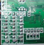
BundPrintplade.jpg
Hope you can use the above picture?

Yours sincerely
Monie
 
monie jacobsen said:
Hi, fechter
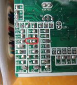
Under PCB layout - red circle = "V" has direct connection to the green cable to the center of the potimeter!
BundPrintplade.jpg
So the connection is OK!
But the speed control system still does not work yet?

Yours sincerely
Monie

I'm confused now. Previously you said the throttle green wire was going to the V pad.

Do both the hall and throttle go to the V pad? Only the hall signal should go there.

I checked my archives of controller data but seems the markings are not very consistent between models. On most of them the throttle signal is marked SP.
 
Hi, fechter
I can not find the throttle signal that is marked "SP".
Do you have another solitary place that can be used?

Yours sincerely
Monie
 
Do both green wires go to the V pad?


The markings on the boards are not at all standardized and every manufacturer uses different ones. Some are obvious, like 5v or Gnd.
The ones that start with "S" (SV or ST?) might be worth testing. One labeled PWM might be another one to try.


One more question: If the throttle wires are not connected to anything, does the motor still run by itself? If it does, then something is seriously messed up with the board as it should default to stop with no connection.
 
Hi, fechter
Thank you very much for responding to me.
Has test "S" (SV or ST?) ... But without result for speed regulation with potmeter.
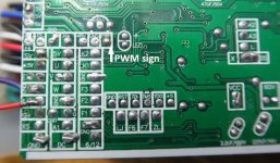
And one labeled with PWM with find square signal shown on oscilloscope!

Motor runs at full speed, even though the throttle wires are not connected to anything!

You can see below on the PCB Layout images:
Bottom PCB-Layout 2.jpg
Bottom PCB-Layout 3.jpg

By the arrow there is a PWM signal, but seems more constant and unregulated!

Yours sincerely
Monie
 
Hi fechter
"Maybe time for a new controller. Ones like that are pretty inexpensive."
Yeah, you're right fechter ...
Can you help me with another BLDC Controller, with the following technical data:
1: Max 48Volt
2: Ca. 300 - 500Watt
3: And with the possibility of using the potimeter;)

Yours sincerely
Monie
 
Hi fechter
Thank you very much for responding to me;)
My located is Denmark...
I'm cautious about buying if more defective BLDC Controller!

Yours sincerely
Monie
 
Back
Top