Switched to a GNG style "big block" swingarm coming soon!!

So envious, would just love to get myself a tig again.. Sold all off when I gave up farming 12 years ago
 
Rodney64 said:
NeilP said:
So envious, would just love to get myself a tig again.. Sold all off when I gave up farming 12 years ago


Still got your farmers hat though.


More African Safari hat..but yes it does get uysed on the farm too..still go the farm , but all rented out for DIY livery ..pays for the workshop
 
I like it HAPPY NEW YEAR ALL!!
 
Weird how that ended up after two posts but thanks guys!
 
Update!

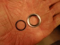
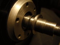
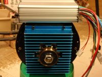
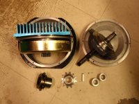
I got the motor apart and it seems quite simple really now that I can look at it. I think simply removing all the circlips except the one on either end of the shaft so they sit against the inner races of the side cover bearings, and using the stator cover to drill the side cover accurately, making a heat bridge that will replace the stator cover and possibly some small shims to keep everything tight inside I should be in business! Here are some pics and vids to show what it really looks like in a MAC


2013-01-01_10-11-01_954.jpg


2013-01-01_10-14-56_33.jpg


2013-01-01_10-23-25_684.jpg


2013-01-01_10-24-01_597.jpg


2013-01-01_10-28-46_463.jpg


2013-01-01_10-33-52_467.jpg


http://static.photobucket.com/player.swf?file=http://vid116.photobucket.com/albums/o29/fuknmovin/2013-01-01_10-11-45_69.mp4

http://static.photobucket.com/player.swf?file=http://vid116.photobucket.com/albums/o29/fuknmovin/2013-01-01_10-35-32_640.mp4

http://static.photobucket.com/player.swf?file=http://vid116.photobucket.com/albums/o29/fuknmovin/2013-01-01_10-39-41_893.mp4

http://static.photobucket.com/player.swf?file=http://vid116.photobucket.com/albums/o29/fuknmovin/2013-01-01_10-55-35_991.mp4
 
Hi,

Whiplash said:
Similar but with the pedal gear on the left side of the bike...
If you put it on the right side, like the Hanebrink:
1. Pedaling with the motor off you wouldn't be forced to turn the motor.
2. Easy to run dual chainrings or a 2-speed BB so you can comfortably assist at a larger range of speeds.

crossbreak said:
I'm waiting keen for this documentation! Even after 20 pages of discussion in the other thread, it's not completely clear for me how to do it. this would be something for the wiki :)
Maybe Paul (cellman) would have them fabbed in small batches?
 
12 screws and less than 1 minute can take the converted to here:

P1010481.JPG

You really only need the circlips on both sides of the clutch. What ever sprocket or adapter you use on the brake side should be pull the clutch circlip up against the bearing inner race. That way the bearing takes care of axle alignment. Leave the axle to float in the FW side. The motor is attached to the FW side. The length of the header/heat bridge only effects the axial alignment of the sun and planet gears. The axial alignment of the planet gears and ring gear is already set by the brake side cover. That way expansion does not effect bearing axial loading. Expansion only effects the axial alignment of the sun and planet gears, and there is lots of room for that :)

bØb
 
Thanks for the tip bOb, I'll likely do it that way then...

Thanks Spinning mags, helping/playing with the tools for the bikes is one of her favorite things! We hope it means she will be a little mech/electrical engineer or something! I plan on pushing one of these! I wish my parents would have stressed school more to me, I would love to be a mech engineer!
 
Had a little time to work on the motor today. I think I have it figured out and yes, I did use the circlips on either side of the clutch and I am almost done with the new stator carrier/cover. I am simply making a new one that will go between the stator and the side cover and I will screw through the side cover, through the new spacer into the stator locking it to the side cover and giving heat an exit path through this new heat bridge as you guys have been calling it. If all works out well, I will make these and stock them for anyone interested in buying one. I'll have pics up when its done..
 
Nice to hear you make progress. Save up one of your "heat bridges" for me :)

Whiplash said:
... heat bridge as you guys have been calling it

I'm sorry, this was just bad translation from German, the right term would be "thermal bridge": http://en.wikipedia.org/wiki/Thermal_bridge

This term is a bit sarcastic, IMHO geared Hubmotors are almost perfectly isolated in stock condition :lol:

Nice to see that there are no holes in the rotor. This way the oil can be kept away from the stator by an additional plastic sheet/seal as you have mentioned before. Also hope to see metal planetarys in your build :shock:

The swing arm pivot point shown here is still not aligned to the chain:
file.php


Why dont you want to align that? Suzuki and Kawasaki do so with great success since decades.
 
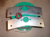
Still need to drill the holes but here they are, if I make any for anyone they will be one piece, I just didn't have the proper thickness stock on hand so I did it in two pieces. I'll thermal paste both pieces and the stator and the side cover so it should be a MAJOR improvement in cooling even without oil cooling. If I can do it without the oil and sustain 2000 watts for long bursts I'll be happy! I think its very doable considering the bike frame will be a heat sync...

photobucket-43576-1357443146149.jpg
 
How thick did yours turn out? Have you assembled it yet? Now if you can circulate water through the bike frame :roll:

bØb
 
crossbreak said:
The swing arm pivot point shown here is still not aligned to the chain:
file.php


Why dont you want to align that? Suzuki and Kawasaki do so with great success since decades.

That one is just a tinker I did, not whiplash's final design, Basically did it for compact options, the rear derailleur should take up any differences in chain tension. There are half a dozen high end DH bikes out there that are not allligned either, so it shouldn't be a problem. I do however have an exo-skeletal design (rather than styled like whiplash's sketch in the first post) in the works I am sketching out, that is almost aligned. If whiplash doesn't mind I'll chuck it up in here as well, he is making a frame, so he can make ANYTHING!

I'm getting interested in a bb hub drive now though, some great things are coming from them, this project included. Keep up the good work Whiplash!

Edit: was thinking, and the best heatsink you could get is probably going to be a thermal bridge between the can and the frame itself. At the very least I would put some transfer putty used in pc boards-heatsink connections where the can touches if possible.
 
Yes I was planning on heat paste at each metal to metal joint in the drive train. Also, pleas post any frame ideas I'm open to anything that has form AND function. I want it to look as good as it works! THX guys!
 
bØb said:
How thick did yours turn out? Have you assembled it yet? Now if you can circulate water through the bike frame :roll:

bØb


I still need to drill the holes and assemble it, but I think I have it right at .730" I used marking grease and assembled the motor, then measured where the cover bearing came to, then I added in the amount that the cover bearing protrudes from the cover to get .730" . I think it'll be close, I might have to adjust it but we'll see...
 
OK I got the spacers drilled and I pre assembled the motor. It seems good but a have a little grinding noise I need to address before I try to spin it up. I am unsure where its coming from but it could slack in the clutch as it IS an old original one with a steel gear so it might be nothing. Out of time tonight but I'll snap a few pics before bed tonight...
 
bandaro said:
That one is just a tinker I did, not whiplash's final design, Basically did it for compact options, the rear derailleur should take up any differences in chain tension. There are half a dozen high end DH bikes out there that are not allligned either, so it shouldn't be a problem.

Sry, i mixed this up :oops: I have no experience with 2-linkers. All my motorcycles and bikes I own are 4-linkers. Had a 2-linker once (125cc Honda Wave) which had horrible offroad capabilities. Still, the 4-linkers have their swing arm aligned to the chain. If I would build a frame I would stick to an existing and proven geometry. There is just too much to loose.
 
I suspect that your spacer is too thick. Or there is a difference between older MACs and newer MACs. My spacer had to be 0.671" thick. My MAC is the newer one with holes in the rotor, new gray gears and even tough it did not have the newest clutch, I built it with one that I had bought separately.

Here is how I determined the thickness of the spacer:
#1 Assemble the clutch and planet gears on the axle with a circlip on each side.
#2 Put the brake side cover on the center section. It goes on the side closest to the ring gear. Just use 3 screws, It's coming back off in just a minute.
#3 Put the axle and planet gears in the housing and spin them. If the clutch does not drag on the brake cover, proceed to next step. If the clutch drags on the cover, try adding a thin shim. If the shim stops the dragging, try placing the shim between the outside circlip and the clutch. You may have to help the circlip seat with a screwdriver. I will explain why I put the shim between the circlip and the clutch later.
#4 Check the axial alignment between the planet gears and the sun gear. The gray gears are wider than the ring gear so they hang over about 1/32" on each side. That's OK just don't leave them lower than the ring gear. Shim at least until the are flush.
#5 Put your spacer and stator on the FW cover. I used the original little cover, but you have to relieve the I.D. a little until it will slip on the axle.#6 Remove the brake cover and install the FW cover, spacer and stator on the proper side. You can use 3 screws again. You can temporarily put the axle, gears, clutch in the brake side before tightening the screws that hold the stator. Spin everything a couple of times to line things up and tighten the screws for the stator. Don't bother with putting screws in the brake cover.
#6 Pull the brake cover off leaving the axle and clutch in place. The planet gears should be aligned below the the top of the ring gear. If not your spacer is really too thick and the rotor is probably dragging on the ring gear.
#7 Pull the axle, clutch and gears out. Lay a straight edge on the top of the ring gear, if you can. If the spacer is too thick the straight edge will lay on the end of the sun gear. I used a 5-1/2" piece of 1" X 1/4" aluminum flat bar that was scrap and it worked perfect. Next calculate for a new spacer. You want the top of the sun gear to be even with the top of the ring gear.

Here are some other thoughts you might consider before cutting the spacer. The FW cover on a MAC is thin and flat. Mine was bowed out. When I added the heat sink on the outside, which is retained by four of the cover screws (longer of course), a lock nut on the FW mount and the six screws screws that hold the stator, everything flattened out nicely. You might consider adding a 1/4" or thicker aluminum plate over your FW cover. You could make it part of the mount for the motor. You might also either Bore the FW mount to 30mm to add a 17mm X 30mm X 7mm seal. Or there are 17mm X 26mm X 5mm seals available, though not as common. Google: 17mm X 26mm X 5mm seal -bearing. The hole in the FW mount is already 26mm :) I don't know what size the hole is in the brake disk mount hub is because I have already removed mine for clearance reasons, but I think you could put a 26mm O.D. seal in it.

About the circlips and maybe spacer with the clutch. I wanted the clutch to be very tight on the shaft because I bored the ridge in the brake dish mount hub out to 1.010" to accommodate a reduced hub sprocket. The axle nut draws the sprocket hub against the bearing inner race and the circlip on the inside of the bearing. This is what keeps axial gear alignment. The axle floats on the FW side, thus the reason for the lip seal. I wanted both circlips and the clutch to draw up at the same time and share load of the axle nut.

Now to seal the bearing on the brake side I made a spacer that is 1" O.D. x 17mm I.D X 3/32" long from a piece of SS shaft. It has a 45° bevel on the bearing side to force a 7/8" O.D. X 5/8" I.D. very soft (50 durometer) o ring against the inner race of the bearing and the axle.This seals the inner race and the shaft. The outer race is Loctited in the cover. This spacer goes outside the motor, on the FW side. I think the bearing seals will retain oil :roll:

P1070482.JPG

P1200494.JPG

Even tough I shortened the threads on the ends of the axle and turned the ends to 5/8" and milled 3/16 keyways, I have become concerned about the radial load exerted to the bearing and covers of the motor. The axle was long enough to get the sprockets and a 14T Left hand FW on. The whole thing could be kept to 135mm not counting nuts. I have made light weight pillow blocks that hold 5/8" X 1-3/8" bearings that will be mounted to my new 1" square chain stays.
PC290469.JPG

I am going to make a longer 17mm shaft that is stepped to 5/8" on the ends. The motor will have a torque arm (shock mounted) for motor torque and the chain pull will be carried by the pillow blocks. The motor will hang between the chain stays, just in front of the wheel. The drop outs are 135mm on the inside and the chain stays are 135mm + 10mm on the inside.

The controller is going to mount on the top of the motor (6" 10 ga. phase wires) with the battery right in front of the motor. 12" battery wires :D

P1010478.JPG

The chain line is 49mm from center, exactly right for a NuVinci N360 later :p

bØb
 
Great info thanks! I'll look into it tonight... My spacer had to be turned down .100" to make everything fit. I clamped the gearboxside axle in the vise and with the gear cover in place, motor assembled, I bolted my cover on the stator and measured the gap in the cover to determine the needed material removal. I think I'll power it up and see what happens before tearing it down that way I can see where its rubbing... if at all.

photobucket-3564-1357569735006.jpg
 
Just curious; in the picture of the motor apart, it looks like the hall sensors are located in the motor slots. Is this the case? My theory is the motors that have the halls located in the slots have an inherent timing advance which causes problems with many controllers. The MAC/BMC controllers designed for these motors takes this into account somehow. Newer motors seem to have the halls located slightly off to one side of the slot.
 
OK I think I found the grinding sound. I didn't have the motor assembly centered in the housing and when the metal gear would rotate, there would be a tight spot resulting in a tight gear mesh just for a few degrees of rotation and it would groan. I moved it around a but and got it much better but I think I'm going to make a centering tool that fits the shaft tightly and the inside of the motor sections bearing bore hat I can just insert with the stator screws loose, and then tighten them up and remove the tool. That way the motor section is properly centered in the housing thus eliminating any unnecessary gear noise. I am also going to order a new clutch and planetary gear set so I can have the newest version for strength and only go with the steel gear if needed...


Basically it was just an alignment issue and should be fine as is... time will tell..

Now I need an Argon tank!!! So I can get to designing/building this frame!
 
Now I need an Argon tank!!! So I can get to designing/building this frame!

Nice to hear. Any Idea about frame geometry? How about asking a friend who owns a great DH bike and measure geometry? And just tweak this given geometry a bit for your need

But first I guess you want to get some practice with your new toy, I'm a bit jealous ;)
 
I'm kind of up in the air there, actually I thought about taking cardboard and making a 2D version so I could play with sizes and stuff, nobody I know has a nice DH bike so I'm kind of screwed there... I think I'll just mock it up in cardboard with swing arm and all in 2D and actually put wheels on it and everything once I get it close to perfect. I can't afford to waste the metal if I make it wrong...and cardboard is cheap!
 
Back
Top