The Barncat Battery- No weld/no solder

This post may be the 25th post on this page so that it will soon be gone with my following post on p.4 showing fabrication photos by monkmartinez hopefully followed by his response below the photo(s) i'll post of his no-weld fabrication. FWIW, here goes with my reply to Hh previous comments to me :( ...
Hillhater said:
.. are you suggesting that a welded pack is no simpler than these “loose cell” packs ?
Hillhater said:
..And incase you had not noticed , Bc’s packs ARE 20s and 15 s ! :roll:
What i was getting at is the end-to-end length of Barncat's design is 5 cells ... so two cell layers could be as much as 10s4Por5P. Thus possibly applicable for e-skateboard use and even some abuse.

It's not as if a DIY spot-welded pack has never suffered from Xtreme vibration. The point being that it takes a very knowledgeable, highly skilled builder to fabricate a DIY spot-welded pack that can withstand the Xtreme vibration that a skateboard or mountain bike has to endure.

Xtreme vibration is definitely a concern with e-skateboard use. Barncat needs to makeup a 10S4P end-to-end design. Give it a good workout using the jumps and bumps experienced with a skateboarder. Maybe, that's what it will take to convince you that his design concept has merit ... even for skateboard use.
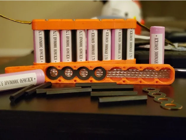
 
Here's another end-to-end pressure contact concept at ES by Ufobox... https://endless-sphere.com/forums/viewtopic.php?t=101439

Here's that previous photo by monkmartinez ... (on page 3 link) copied from another website ...

e089b3efa2767ee7d01780834c4eb991e2214802.jpeg


and 4 other thumbnail photos by monkmartinez from website. Can be enlarged for closer inspection ...https://www.thingiverse.com/thing:3574079 ... and more of his concept photos ... https://www.thingiverse.com/thing:3574040/makes

Hopefully monkmartinez will read your post to him ... second from the bottom on previous page
 
Great job Barncat! :bigthumb: Awesome thread! Good to see another weldless design contribution and success story. Lots of great ideas for others to use, and your time proven validity is inspiring.

It's the inventors plight to be dis'd, and yet, everything we have is an invention! Go figure.

I have nothing against welded packs, other than I would rather not,.. and it entirely depends on the use-situation. I would point out that these cells were made to be contact first, and the welding came later. My ancient A123 drill packs had springs for contacts. The RC guys started soldering, and then welding became popular.

Pressure packs may be a bit larger and heavier at the moment,.. still evolving, but nobody can deny the beauty of being able to completely change out cells in just a few minutes!

Anyway, the big question on my list is min/max contact pressure specs., seems to be the only unknown.

Thanks for sharing your designs, and keep up the great work!
 
I think there is a huge market for a power back-up pack for a home, in the 48V-52V range. When everything is going well, we might use "X" amount of kilowatts of energy each month, but I live in tornado country, and it's not unheard of for a wind-storm to knock out power for days, if not weeks.

In that situation, the average person will suddenly re-prioritize their power needs. If someone needs to refrigerate their insulin, then a chest fridge can be a low power device to act as a refrigerator with the temp adjusted to the proper range, and air conditioning can be secondary. Such a person might find themselves using 1/10th the amount of energy they normally would use, but it is the most vital tenth.

I have recently moved, and one of the new purchases was a large chest freezer. Since cold sinks, having the opening on top means that frozen foods can stay frozen for a VERY long time after the power goes out. Even after the frozen goods start to thaw, they are still cold enough to remain unspoiled for an extended time.

A DIY battery pack using pressure contacts is a fantastic home back-up. There is a reduced risk of contact corrosion, and there is no heating-cooling cycles (like a garage) and there is no vibration of sudden pothole shocks.

I want endless-sphere to be the hub for this type of information. If this design works well for Barncat's ebike, sweet. But even if it has enough issues that he upgrades one part of it, the pics and the discussion are saved here for thousands of readers, who will come here because of a google search on this subject.
 
APL said:
Great job Barncat! :bigthumb: Awesome thread! Good to see another weldless design contribution and success story. Lots of great ideas for others to use, and your time proven validity is inspiring.

It's the inventors plight to be dis'd, and yet, everything we have is an invention! Go figure.

I have nothing against welded packs, other than I would rather not,.. and it entirely depends on the use-situation. I would point out that these cells were made to be contact first, and the welding came later. My ancient A123 drill packs had springs for contacts. The RC guys started soldering, and then welding became popular.

Pressure packs may be a bit larger and heavier at the moment,.. still evolving, but nobody can deny the beauty of being able to completely change out cells in just a few minutes!

Anyway, the big question on my list is min/max contact pressure specs., seems to be the only unknown.

Thanks for sharing your designs, and keep up the great work!

That era of early welded RC packs used aqueous electrolytes in NiCd and NiMH cells. The phase change energy of water and high-temperature fiber separators in those cells made them ideal for welding without imposing thermal damage. Its unfortunate carbonate ester-based electrolytes do thermally decompose without significant temperature buffering in phase-change energy.

Thermal expansion and contraction over time makes small relative motion between surface interfaces, and varies clamp loads with temperature. In wood humidity has some effects as well, but the least expansion on the long axis with the grain. If you absorb water adequately into wood it enables sustained electrolysis through the humidity pathway, but if you live in a dry place and only ride in fair weather it maybe wouldn't matter. A good electric gel coating all your pressure interfaces perhaps would displace humidity well enough to avoid surface corrosion effects from dissimilar metal interfaces. I personally never like to trust the upper heatshrink on cylinder cells not to creep or chaffe through enabling the shoulder of the can to short to positive connection. Many off the shelf thin fiber-washers and plastic washers are sold for adding a second dielectric protective layer from shoulder shorts, also calandared Nomex paper sheets between the stacked cell layers might make the setup safer against long-term chaffing protection. My preference is bottom cooled singled sided wire-bonded interconnects with a monolithic polymer encapsulation, but its almost impossible to DIY that, so folks gotta do the next best options they have the time and skills and materials to safely build. Batteries can be so kind and gentle until the moment they're not, keep safety as a guiding light on every decision in your pack design, then treat it as well as you can over its lifetime, and maybe if you did a great job with everything it will stay gentle over its useful life.

For our battery recycling company, most of the packs we receive did not wear out the cells useful capacity, but failed from inadequate corrosion protection or chaffing and connector-related issues. This is a common trend we see with automotive-sized packs to tiny kick-scooter packs.
 
Jesus, I didn't even think about home powerwall storage.

... can you post more pics about how you make the "chain" between cells? Now I'm super interested for a home powerwall.
 
CONSIDERABLE SHOUTING said:
Jesus, I didn't even think about home powerwall storage.

... can you post more pics about how you make the "chain" between cells? Now I'm super interested for a home powerwall.

Oh no... you can't do that.

Earthquakes. You see an earthquake could happen at any time and cause a dimple in the cells. :lol:

No. I think "Fear and Avoidance" is your best option.

The idea of being able to assemble large powerwalls this way must be ruled out.

And don't forget airplanes crashing into your house. At any moment it could happen.

Let's not even begin to discuss meteors...
 
CONSIDERABLE SHOUTING said:
Jesus, I didn't even think about home powerwall storage.

... can you post more pics about how you make the "chain" between cells? Now I'm super interested for a home powerwall.

If you need kWh amounts of energy, why start with cells that hold a few Wh? Use a cell format that makes sense for your application, and then you don't have to consider options that will give you an another crafting hobby to maintain.

https://batteryhookup.com/products/ford-24s-3-3kwh-ev-module-screwdriver
 
Chalo said:
https://batteryhookup.com/products/ford-24s-3-3kwh-ev-module-screwdriver

BatteryHookup has some amazing deals.

I agree... as long as you can get discount priced large capacity cells it's better to go that way.

But imagine rather that $100 per kWh having to pay $250 per kWh which is probably the list price. (if not more)

The only way you might do a pressure contact battery for a powerwall is if you had a bunch of cells already laying around and just wanted an easy way to put them together.

All you need is some wood, some braided interconnects and some bolts on the end. Pretty easy.
 
SafeDiscDancing said:
Chalo said:
https://batteryhookup.com/products/ford-24s-3-3kwh-ev-module-screwdriver
The only way you might do a pressure contact battery for a powerwall is if you had a bunch of cells already laying around and just wanted an easy way to put them together.

All you need is some wood, some braided interconnects and some bolts on the end. Pretty easy.

Dat be why lol, I have tons of random ass laptop cells and some scrap UPS'es that could make for neat little projects.
 
liveforphysics said:
I personally never like to trust the upper heatshrink on cylinder cells not to creep or chaffe through enabling the shoulder of the can to short to positive connection.

Don't mean to hack Barncats thread, or get off topic too much, but yea the shoulder chaffe thing sucks. Recently I just started on an idea that sort of takes advantage of that arrangement. It's the old light bulb screw-in idea all over again, and not really thought out yet, but for what it's worth.... :oops:

Socket cell holder.png

(cell in pict. is reversed, and socket needs threads yet)
 
As a few of you guys already know, I had a bit of an episode yesterday with the HI200 ESC on my Blackcomb build instantaneously going up in a ball of :flame: . Not good, to put it mildly...

The good news however is that my gray 21700 pack survived the 60 second immolation with zero damage. Just a bit of expensive electronics soot that I can clean off. So I can legitimately add Trial By Fire to the attributes of my packs. Alert U.L.! (I doubt a poorly enclosed heat shrunk pack would have fared so well... ) There's a thread over in the Motor section.

Anyway, glad all are enjoying the debate and that comments are lively. It would be nice if these relatively high energy cells were safer and easier to manipulate. People are working on it...

liveforphysics- yes, I bought and tried both fiber and plastic shoulder washers, but in this application the cathode being a couple thou proud of the shoulder overwrap is more important. As mentioned earlier in the thread, shorts there were my main concern. Not thus far an issue as it turns out, but careful handling, vigilance and routine monitoring of pack health is required, including a quick tear down if anything seems suspect. (Edit- there are full size sheets of .032" polycarbonate as insulating separators between each layer of cells. Plus I don't ride in the rain).

And as mentioned the intended use case is street not off road. One could even rubber mount these packs. I have the most miles by far on the green pack atop the quick steering Mongoose Girder build, which is a way stiff frame, so pack has seen plenty of vibes. The HDPE/poplar/polycarb construction sucks that up quite well.

The light full suspension Blackcomb handles like it's glued to the road and is even friendlier to the battery pack, but alas, that's now sidelined per the fet/cap BBQ...
 

Attachments

  • 20220219_134149.jpg
    20220219_134149.jpg
    3 MB · Views: 740
  • 20220219_134158.jpg
    20220219_134158.jpg
    3.2 MB · Views: 740
That is a shame. Seems like the small controllers just cannot sustain those claimed power numbers for very long without serious heat management, which I would have bet was plenty hanging off the side in the moving air.

Another thing about the solderless design that no one mentioned is the inherent benefit (or perhaps necessity to think about it another way) of being able to easily pull out individual cells or parallel groups. In this design, you can take all of them out as easily as they went in to inspect every 100 miles or every other trip if you want. Main thing is to not cause a short when disassembling, which is also a concern with a welded or soldered pack. Also the beauty of the simplicity of the design is as soon as you see something swelling or deforming or corroding (not terribly hard with transparent sides) you can replace the wood frame or the braided copper or the screws. Those materials are still affordable in large quantities during the COVID economy, for now.
 
Barncat said:
monkmartinez- very good. You've already done some work in this area. Did you arrive at using the braided copper strip on your own or by seeing it used elsewhere?

I saw this design being used in eskate boards. I had recycled cells that I did not trust and wanted to be readily accessible if needed. The eskate folks are an innovative bunch in my experience. They have a section on their forums call "shitty DIY and nothing else"... well, that sort of thinking is right up my alley. I have more money than time these days, but I am frugal to a fault. This was the quickest way for me to get started.

Barncat said:
The side walls and end walls must be very stiff. The clear polycarbonate (Lexan) lid pegs the cool meter, and the see-thru cells are the first thing people notice when commenting about the bikes out on the street. Humorously, many people have asked "is that solar powered?"..........

Polycarbonate is a miracle material IMO. DO NOT, I repeat do not, use shatter prone acrylic instead for the lid- that stuff has no place in this application- and I never use it for anything. Poly is explosion and bulletproof in adequate thickness, is easily drilled, sawn and shaped. It's not very stiff however, hence the aluminum angle straps on the wider gray pack.

Reread my posts for construction and tolerance specs. Avoid shims. Absolute minimum clearances must be held- easy once you know your printer, which must be able to do at least 16" one way for 5s/layer.

I have 20 - 3mm Lexan (polycarbonate) sneeze guard sheets that measure 36"-ish x 24"-ish that I picked up at a local auction for $1 each. These will be incorporated some how into the pack. In the time after my ebike build, I managed to complete a DIY CNC router. I don't intend to use my 3D printer much for this build. I can hold nice tolerance with the CNC...


Barncat said:
Whole case is top loading with all internal and external buss plates in place and screws backed off. Be damn sure you design the internal plates (which are hand dimpled for contact) to be captured so they can't move and short your whole pack.

Lay in the bottom layer of cells and parallel strips, add the
.032" Lexan insulator sheet, reverse cell orientation and lay down second layer, etc.... when you're done the top layer of cells should be about .005" proud of the case sidewalls (which allows the whole stack to clamped down). Screw the lid on snug enough to keep all cells flat and such that they can still move longitudinally. Adjust the screws and lock nuts from the bottom row up, then screw lid down tight. This all takes skill and feel. And used cells must be burr free with old weld tabs carefully removed and make sure the + ends have no flaws in the overwrap insulation. I do not use additional fiber or plastic ring washers.

Also since you're printing- add projecting insulator fins between the external copper bus plates.

You have your work cut out for you. A lot of measuring to do!

Fantastic... this explanation along with the pictures should be enough to put my own spin on the design. I have to draw the thing in CAD before I do anything else.
 
10-4 and good luck. Proceed at your own risk of course.

Don't forget my tip about cutting the overwrap off the negative cell ends for best contact- tho that's an "irreversible" decision. If you're using flat copper braid for the parallels, you could possibly add an insulator washer on the plus end but that varies...
 
Hillhater said:
Barncat said:
Hillhater- your inference here is that DIY lithium ion packs with literally hundreds of spot welds and dozens of tiny soldered wires connecting fragile circuit boards all contained in dubious insulation and questionable enclosures is 100% infallible.

To put it charitably- that's not true.
Nothing is infallible, but yes, multiple spot welds ( per contact) are much more reliable that a dry pressure contact,..
...but incase you had not noticed , your 20s,5p pack has 200 “dry” connections !
..and all things being equal all packs will need similar balance wires and BMS boards...if that is your point.
Welded packs do not require the same rigid supporting enclosure... and are frequently assembled using simple cell holders..
( and cell bonding is also commercially proven !

There are plenty of dry contact examples if you think. All fuses, relays, switches etc etc use dry contacts and there are billions of these used everyday and not just low power. As someone said there is a valid question what happens to the electrolite whe weld is made and there is that heat problem concerning corosion. I had inspected couple segway packs that are built like tanks with gaskets and waterproofed which had multiple coroded cells.
You say you dont need a rigid enclosure for these spot welded packs vut you really do. Micro movements weare out the welds. Its the same when you solder your terminals and not properly crimp them. Dry contact allows cells to seat properly even if there is some movement given that its not jackass contraption. I am using my system for four years without any issues. I'll wait till its five and then take it apart to see how things are reg corosion.
 
agniusm said:
Micro movements weare out the welds. Its the same when you solder your terminals and not properly crimp them. Dry contact allows cells to seat properly even if there is some movement given that its not jackass contraption. I am using my system for four years without any issues. I'll wait till its five and then take it apart to see how things are reg corosion.

Welding is an "all or nothing" proposition that runs the risk of partially damaging the cell.

Pressure contact connections of a crimp or other type allows the current to continuously "dig" it's way closer and increase connectivity and lower resistance.

Basically the better connection techniques also "get better" with time... lowering resistance.

The reverse is a non pressure "flappy" weld that starts to weaken and then the current gets desperate to find a pathway and starts to eat at the "bridge" it has available until that "bridge" evaporates. The "bridge" is the weld.

I try to think of it like a stream... the current wants to go somewhere and if it's in a confined channel with pressure on the walls keeping tight containment then the water will etch the walls as needed.

But with a stream that is in a flat plain with nothing holding it in with a pressure of confinement then the water will want to meander about randomly disrupting the intended path. And if no exit can be found the flow simply stops.

Pressure contact connections are like a stream with granite sides... the stream isn't going to change direction.
 
Hey guys- yes, in my very first post in this thread I described why, for me at least, a welded pack was not preferable.

After you go through the painstaking DIY process of cutting/shaping and spot welding all those tiny flimsy nickel strips together- you're really only half done. Then it must be insulated and safely enclosed and attached to your ride. And don't kid yourself that those snap together plastic cell holders are robust and prevent cell movement... Plus, as we speak the debate still rages over the poor conductivity of nickel and how to incorporate copper. My system is 100% copper, save for the screws which could instantly be swapped out if I get around to it. footloose and I discussed that earlier in the thread... Manufacturers with robot welders and injection molding aren't really relevant to this discussion.

I took the green pack (@ approx 1800 miles) apart again two days ago for inspection. Zero degradation of cell overwrap on any of the 100 cells, including the all important plus end shoulder wrap. There is no corrosion at all, and I live 1/4 mile from the Gulf of Mexico. All I did was re-polish some light normal tarnish off the parallel strips.

I can safely say that only 2 potential issues give my design less than a 98% or so safety rating: monitoring for continuity and guarding against cathode deformation.

The former has happened maybe 3 or 4 times and presents as an interior group getting more than .05V higher than the rest (the most (+) and most (-) group sometimes run a bit higher on charger). You then disassemble and check individual cell V and rebalance and readjust as need be. You need to stay involved with this pack. Disassembly would be way harder with a BMS.

The latter just involves manual adjustment skill.
 

Attachments

  • 20220221_135456.jpg
    20220221_135456.jpg
    3.9 MB · Views: 569
I decided to add an aluminum angle stiffener to the green pack the other day. The 3/8" thick Starboard end wall was starting to bow a bit over time from resisting the force of 20 screws, which is not good. There's already a stiffener on the opposite end wall. So problem solved. Had to make a new guard cover also.

It actually makes a lot if sense to just print the two end walls rather than the whole case. Easy to do on a regular sized printer, and printed horizontal fins with small fillets would both stiffen the ends and provide insulation between the copper buss plates on the adjustment end when using metal tools. Also a lot easier to print the hole pattern than to drill it all accurately.

One might question the use of hardwood at all in such an object (do not use plywood), but it holds screws well, is cheap, light, stiff, non-conductive and vibration damping, and would hold up a bit longer in the event of a fire disaster than plastic would. Just don't get it soaked in the rain... and the Starboard base works well.
 

Attachments

  • 20220228_095907.jpg
    20220228_095907.jpg
    7.3 MB · Views: 518
What about thin ridgid fiber spacers between cell sides to prevent actual side-to-side cell contact?
Maybe they just aren't necessary even if the additional increase in enclosure width is only 1/2" (5P).

Any other mod suggestions since 2/22 posts? My next project build winter 23/24 10S3P (2170 cells).

Has anyone else built or presently building this same end-to-end fabrication -- please post photo(s).
 
eMark- no, you don't want spacers separating each cell in a parallel group. The negative steel cases per group are by definition already in electrical contact through the copper strip at each series connection.

What you don't want is neg/neg contact between different parallel groups, which is why I use .032 polycarbonate sheets between cell layers. A couple pics previous above shows the flexible shelf liner material I initially used as insulating separators- since switched to lexan.

Both packs are still working great.
 
Super cool info! This is what I need to stick all my loose 18650s into for a Rocket Pocket!
 
Hey Spheroids- I'm nearing completion of my third, most powerful, and probably last battery pack build- 20s5p brand new Molicel 21700 p42a's. The previous two packs have been in regular use since they were built and have been subjected to everything road riding can throw at them, with the notable exception that I never ride in rain.

I'm using stiffer 1/2" thick HDPE end walls on this pack, and went the extra mile to turn custom 8-32 solid copper lamp style screws for max conductivity to the buss plates. Otherwise construction is the same.

These three cases should last a long time, and all cells can be easily swapped out for new ones in the future.
 

Attachments

  • 20240218_174621.jpg
    20240218_174621.jpg
    1.7 MB · Views: 17
  • 20240218_172730.jpg
    20240218_172730.jpg
    1.8 MB · Views: 17
  • 20240218_172923.jpg
    20240218_172923.jpg
    1.9 MB · Views: 17
  • 20240218_172828.jpg
    20240218_172828.jpg
    6.1 MB · Views: 19
  • 20240210_140150.jpg
    20240210_140150.jpg
    4.1 MB · Views: 18
  • 20240208_172955.jpg
    20240208_172955.jpg
    2.8 MB · Views: 18
  • 20240208_172934.jpg
    20240208_172934.jpg
    7.1 MB · Views: 19
  • 20240208_145703.jpg
    20240208_145703.jpg
    1.3 MB · Views: 16
  • 20240208_145645.jpg
    20240208_145645.jpg
    6.9 MB · Views: 19
  • 20240207_163828.jpg
    20240207_163828.jpg
    7 MB · Views: 17
Very nice idea and execution. Ability to disassemble a battery easily is a big advantage,especially for DIY builds.
Recently i thought about somehow mixed idea - build a modular battery from just parallel sections. These could be reliably made solderless, just on mechanical contacts, and pretty immune to any internal short circuits. Then just connect the modules with some space-efficient connectors (also solderless). Something similar to such popular holders, but with 4 layers (or 2, or 1..), and different widths, and connectors/terminals on both ends. But it could also be made 'your' way - that is, every section combines 2 or 4 parallel groups running in opposite directions + some terminators at ends.

1708371808336.png
One question - looks like every 'string' of 20 cells in series is only connected to other strings at box end walls, so like every 5 cells in series there's a parallel connection. Am i right?

The other advantage is that both battery terminals are at the same end, and BMS/balancing wires could be run between the cells (if design allowed for some pass-thru holes) without too much chaos
 
Last edited:
rafalg- Thanks. My design is somewhat difficult to build from scratch due to the tight tolerances required, but would be great for injection molding (impractical, too $$$) or a big printer.

Near the top of page 3 in this thread is a good look at the inside of the case. Each group of 5 cells down the line is paralled with either a copper strip (18650 pack) or braided copper strap (21700 pack) simply laid crosswise, which also acts as the series connection. Due to the foldback at each end the copper buss bars must be 2 cells high.

The idea you're considering experimenting with has already been done. Look at NESE cell holders.
 
Back
Top