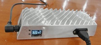
The Cycle Satiator, universal charger for the enthusiasts

A few people have been asking about output connectors on the satiator. We have each unit come with a 1m cable that terminates into a 3-pin male XLR, which is relatively common with turn-key ebike battery packs but significantly less so with DIY batteries. So with each of these beta units we'll also add an XRL->Anderson adapter into the same adapter as the programming cable, like so:
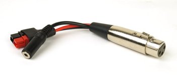
XLR to Anderson.jpg

That should be more convenient for a lot of people. It also in principle allows us to do realtime data logging of the charger from the communications port. It's not something that we've implemented in the user firmware yet, but we do have a debug output stream that could be useful for any diagnostics recording during the beta process.

If you have your own custom charger wiring, it's worth noting that the satiator estimates the losses from the cable lead resistance to the pack and compensates for that on the output. So if at 8 amps it assumes there is 0.4V lost on the charger output leads, then it will put out an extra 0.4V at the source so that at the battery proper it has the desired voltage. In the final firmware this lead resistance will be programmable so you can change it to match any custom lead wiring, but at the moment it is fixed in code.

-Justin
 
Hi,

Ypedal said:
Any chance 2 of these chargers could be used in series?
Any chance 2 or 3 of these chargers could be used in series?
justin_le said:
But I can promise you all this, if in the first year we do super well with the 48V 8A Satiator, then next on the roadmap for sure will be a 72V 5A variant and we'll jump through whatever hoops are needed to make that happen. Even though none of the cheap china chargers have any UL / CSA listings and people here seem fine with that, as a north american company with liability insurance coverage and all that we've got to do everything by the book.
justin_le said:
Yup, but series connection would still generally require a mid-point tap on the pack. So if your 72V or 96V or whatever setup is made of two 36V or 48V packs in series, then each pack just has its own charging port and it will work fine. But if you have a single monolithic battery at this voltage without access to a mid-point reference tap, and then wanted series connect the satiator outputs into a single + - connector that is 72V, that gets quite a bit more complicated and wouldn't be recommended.
But if you can make that work, you could sell the chargers without jumping through any extra hoops, because that would be an unsupported feature. You could even put a sticker on it warning users not to do it :). I don't know how difficult it is to implement the necessary electronics, but wouldn't it be worth it to avoid the regulatory hassles?
 
justin_le said:
John in CR said:
With the word "Universal" my wishlist would include accepting variable DC input as low as 30-50V with the unit able to effectively handle the variances of solar panel output. :mrgreen:

It definitely works OK at 90V DC, so if you can double up a pair of these solar outputs in series it should do. I'll check later today on just how low of a DC voltage the PFC input can properly handle, even if at somewhat derated power outputs, we might be able to go a fair bit lower still as a lot of people have found running laptop adapters etc. off their 72V packs. My own "universal" wishlist also included the ability to work in reverse, taking the battery and stepping that into a 120V / 220V output AC sinewave inverter, either to run equipment or do discharge load tests on a battery by dumping the energy back into the grid. But even though most of the power components are there for that, some of the key control parts don't function bidirectionally. :cry:

I can get to high enough voltage easily. I worry about current. Since it's designed for plugging to the wall where supply isn't an issue, will the variations in voltage and current strain the unit? As solar continues its rapid expansion, making the charger flexible enough to deftly handle the intermittent input of solar panels seems like a good idea. I'm typically cheap with things like chargers, but for this kind of flexibility I'm willing to get spendy. 8)
 
MitchJi said:
But if you can make that work, you could sell the chargers without jumping through any extra hoops, because that would be an unsupported feature. You could even put a sticker on it warning users not to do it :). I don't know how difficult it is to implement the necessary electronics, but wouldn't it be worth it to avoid the regulatory hassles?

One complication is that you can't have two constant current devices connected in series. So you need to have one charger always in CV mode, while the other is operating in CC and then eventually does the CC->CV transition. That's not the end of the world, but it messes up a lot of the more advanced features like the internal SOC estimator (one charger sees full voltage right from the start, the other sees double the voltage change during charging as it normally would). During charging, the satiator occasionally turns off and on the output for a second in order to re-zero the current amplifiers and cancel out any thermal drift, (and in future FW also estimate the battery's internal resistance). When one charger turns off briefly, then the other will see it's voltage max out and current fall to zero causing to to enter a charge complete state.

And again towards the end of the charge the satiator periodically disables the output to check whether or not a battery is still connected to the port. I'd need to think through the consequences with series connected devices of having one disable the output while the other is still driving a current.

Aren't most people currently with 72V or higher setups still assembling and also charging them as two lower voltage modules in series? I haven't seen very many ebikes that used single monolithic 72V batteries, but it's been a while since I've been active in that scene ;)
 
Ypedal said:
You mean.. like this :
https://www.youtube.com/watch?v=6j6tWLOQ148
Super Ghetto.

Yeah. The way you did it is right on, you have one power supply (or in your case 3 in series) that is basically a constant voltage source, and that is in series with a smarter control power supply that does the current limiting and final voltage rollback.

Anyways, I really dig the ghetto setup too, but at this stage was feeling like the performance ebike scene was deserving of some "non ghetto" options as well, which you'll get to see soon enough Ypedal! We won't be shipping out today just pending one more firmware tweak related to end of charge behavior when the BMS circuit trips abruptly, but it's just about there.

We're going to post a more an updated and more formal sign-up sheet for beta testers in just a little bit if there are others following this thread who want to be aboard.
 
Justin, this is a very nice charger. Good looking, too.

However :) What I would like it to have is a port with digital and analogue interface for voltage and current control. Now that would make it truly universal and possible to integrate in to advanced systems. Now it looks to be focused only to DIY market, where guys bother looking at it's screen and pressing buttons. I mean, what if I have advanced BMS and would like to be able to regulate charging current during balancing state, to get a real CCCV mode,vinstead of jerky on-off'ing?
I understand it is too late to change anything, but it is interesting to hear your reasoning :)
 
very interesting. i built a couple of "single brick" 20s batteries ATM with differenct 18650 cell chemistrys http://endless-sphere.com/forums/viewtopic.php?f=14&t=59940
Also bulk charge it in CC-CV mode. The balancing does the BMS, also cell voltage HVC and LVC.

I built my backs with a "middle output" at 10s so i can check on lower and upper cell voltages during built process using an EOS1420i. But I can not fully charge it that way since the BMS would start balancing down the one half pack with higher SOC.

Still i think your 60V limit seems reasonable due insulation issues at higher voltages. This is a lot more effort with the 72V systems
 
This thing actually looks really awesome :D I'm quite interested, but unfortunately don't (as of yet) have the $300 to shell out. I'm starting work on a modified stand-up escooter build with a plan to run 16s8p LiFePO4 (52.8V nominal, 59.2V fully charged, 20Ah), and a 48V 8A charger that can be mounted to the scooter and plugged in on the go with minimal risk of fire or self-destruction would be wonderful.
 
Its just really heartwarming to see some folks working on stuff like this that really care about the future of this "sport", way of life actually, that combines so many elements of fun, capability, mystery,community, social responsibility, ecological awareness, and genuine humanity. I'm going to love my satiator, if I don't break out in tears of joy beforehand, to have a charger which DOESN'T SUCK. Next week...maybe some day I will be able to run it backwards so I can clean up my yard with my electric chainsaw off my ebike. A combined charger inverter. One can dream?
 
circuit said:
Justin, this is a very nice charger. Good looking, too.

Thanks! Some of the earlier iterations were a little less attractive:
Early Satiator.jpg

However :) What I would like it to have is a port with digital and analogue interface for voltage and current control. Now that would make it truly universal and possible to integrate in to advanced systems. Now it looks to be focused only to DIY market, where guys bother looking at it's screen and pressing buttons. I mean, what if I have advanced BMS and would like to be able to regulate charging current during balancing state, to get a real CCCV mode,vinstead of jerky on-off'ing?

Well, I'm interested to hear you flush out your thoughts a bit more. I have a lot of pent-up anxiety about ebike or EV systems that have too much co-dependency and inter-component communications, maybe coming from seeing the downsides of this firsthand dealing with proprietary setups. The behavior you describe only happens if you have pretty widely unbalanced cells and/or a BMS over voltage cutoff threshold that is too low. With an "advanced BMS" as you describe, you should be able to set the upper voltage trip at like 4.25V/cell, while the charger CV mode is at like 4.15 V/cell, and then you can still have a noticeable deviation at the end of charging without causing the BMS to trip. In this example, one cell could be 4.25V, while it's neighbor could be 4.05V, the charger is in CV mode, the 4.25V cell is slowly bled down by the BMS and as it does this an exactly matching current comes out of the charger topping up the 4.05V cell until they are both level at 4.15, no special control needed.

Even if it does cause it to trip and then release the BMS circuit, the total time it takes to get into balance is no different than if it was done with a steady trickle. So there is no actual benefit to having the charger current regulated by the BMS, at least in terms of total charge time.

I understand it is too late to change anything, but it is interesting to hear your reasoning :)

Well there's no chance of providing analog control of the charger's output, but the purpose and utility of the 3rd pin's digital communication bus is still unimplemented. So it would be possible to have a digital input control to command the charger to do things if some application wanted it as a slave device. I was thinking this might come up in cases like fleet charging applications, or for a business/oem that was running automated charge/discharge testing of battery packs for life cycle analysis or that kind of thing. In your case is it just BMS control of the charger output that interests you or were there other schemes too?
 
ARod1993 said:
This thing actually looks really awesome :D I'm quite interested, but unfortunately don't (as of yet) have the $300 to shell out.

I should just clarify that the beta program devices are $250, and that's including the adapter cable to andersons and the USB->TTL, in case this is a deciding factor for some people. Production batch MSRP will be $295. There are some slight differences on the label and a few internal components but functionally no difference.

chvidgov.bc.ca said:
Its just really heartwarming to see some folks working on stuff like this that really care about the future of this "sport", way of life actually, that combines so many elements of fun, capability, mystery,community, social responsibility, ecological awareness, and genuine humanity. I'm going to love my satiator, if I don't break out in tears of joy beforehand, to have a charger which DOESN'T SUCK. Next week...maybe some day I will be able to run it backwards so I can clean up my yard with my electric chainsaw off my ebike. A combined charger inverter. One can dream?

Hey Chris, we'll be really happy to get this in your hands too. In my dream future, your electric chainsaw will also run at 36V/48V DC, and you can interchange your chainsaw battery for your ebike battery and visa versa with any other electric gear, no inverters ever needed since this will be the new voltage standard for all kinds of devices.
 
liveforphysics said:
Does the output have galvanic isolation from input?

Indeed, very good galvanic isolation at that.

If so, and you also have the capability to drive current at low voltages, your device could be programmed to know the voltage of CV supply/s and do higher voltage packs just fine. It could work for the 84S pack in the Palatov. If you want a tester for its use in a medium HV (345vdc max) pack, I volunteer and have a suitable CV block already. :)

Hmm, what's the total voltage swing from flat to full on your 345V system? This is a cool thought, you tell the satiator that there is a 285V CV supply in series with it, and then on the display screen it just adds that to its own output voltage. You would see an estimate of the pack voltage on the screen, though the satiator just looks at managing the delta voltage swing (from say 300V up to 345V in this example). Maybe like a V2.0 firmware feature (now we're at FW 0.802), but I can see that being a handy way to make use of an inexpensive CV power supply for most of the power and then the Satiator for all the charge management and other features.

Only issue that comes to mind is what happens if the CV power supply is turned off or fails, we'd need to make sure it doesn't present 0V or else there would be some 300+ volts across the satiator's output leads which it wouldn't like.
 
justin_le said:
liveforphysics said:
Does the output have galvanic isolation from input?

Indeed, very good galvanic isolation at that.

If so, and you also have the capability to drive current at low voltages, your device could be programmed to know the voltage of CV supply/s and do higher voltage packs just fine. It could work for the 84S pack in the Palatov. If you want a tester for its use in a medium HV (345vdc max) pack, I volunteer and have a suitable CV block already. :)

Hmm, what's the total voltage swing from flat to full on your 345V system? This is a cool thought, you tell the satiator that there is a 285V CV supply in series with it, and then on the display screen it just adds that to its own output voltage. You would see an estimate of the pack voltage on the screen, though the satiator just looks at managing the delta voltage swing (from say 300V up to 345V in this example). Maybe like a V2.0 firmware feature (now we're at FW 0.802), but I can see that being a handy way to make use of an inexpensive CV power supply for most of the power and then the Satiator for all the charge management and other features.

Only issue that comes to mind is what happens if the CV power supply is turned off or fails, we'd need to make sure it doesn't present 0V or else there would be some 300+ volts across the satiator's output leads which it wouldn't like.


1kV diode on output? Ideal diode?

348v fully charged, 290v fully discharged, but with 30kWh on such an efficient vehicle, I could just jumper one of the isolated series supplies into hiccup mode and change the charger settings for the few trips a year I may actually have pack SOC below 300V. I imagine >99% of its trips would be charge sated by it. I dont need anything more than a CC/CV mode to get it running initially. I have adequate diodes to prevent the stack being fed from the pack if a CV supply dies.

Perhaps there is an input available on the board that when passed through an appropriate divider network could be the offset CV voltage sense tap. That would let it compensate for restive voltage drop as well. Then it wouldn't require even programming the offset voltage, and for the ebike hotrodders they could just stick a cheap 48v or 72v CV supply or whatever they need under it.

Warranty voiding firmware Easter-egg?
 
justin_le said:
However :) What I would like it to have is a port with digital and analogue interface for voltage and current control. Now that would make it truly universal and possible to integrate in to advanced systems. Now it looks to be focused only to DIY market, where guys bother looking at it's screen and pressing buttons. I mean, what if I have advanced BMS and would like to be able to regulate charging current during balancing state, to get a real CCCV mode,vinstead of jerky on-off'ing?

Well, I'm interested to hear you flush out your thoughts a bit more. I have a lot of pent-up anxiety about ebike or EV systems that have too much co-dependency and inter-component communications, maybe coming from seeing the downsides of this firsthand dealing with proprietary setups. The behavior you describe only happens if you have pretty widely unbalanced cells and/or a BMS over voltage cutoff threshold that is too low. With an "advanced BMS" as you describe, you should be able to set the upper voltage trip at like 4.25V/cell, while the charger CV mode is at like 4.15 V/cell, and then you can still have a noticeable deviation at the end of charging without causing the BMS to trip. In this example, one cell could be 4.25V, while it's neighbor could be 4.05V, the charger is in CV mode, the 4.25V cell is slowly bled down by the BMS and as it does this an exactly matching current comes out of the charger topping up the 4.05V cell until they are both level at 4.15, no special control needed.

Even if it does cause it to trip and then release the BMS circuit, the total time it takes to get into balance is no different than if it was done with a steady trickle. So there is no actual benefit to having the charger current regulated by the BMS, at least in terms of total charge time.
My company is specializing in industry BMSs. We do support "CAN-enabled" and "non-CAN" chargers. With non-CAN chargers, we have observed such jerky operation: when battery pack is close to fully charged and some cells are hitting "fully charged" voltage, there is nothing else for BMS to do but to cut off charger, bleed down the cells and switch charger on again. It works OK at first, but when some cells are very close to 100% SOC, they have a quite high impedance. So, when charger is switched back on again, it instantly hits overvoltage condition, which is above "fully charged". I have not done any study to see how this impacts total charging time, however it is obvious that such operation is stressing cells.
This can be somewhat worked around by slow ramp up of current. But that would add some balancing time.

Currently we support eltec and elcon chargers over CAN. However these are quite high voltage. Time to time we get clients asking for CAN-enabled chargers for 24-48V systems and really don't have what to recommend. There is a gap in this field. A $350 CAN-enabled charger would be very desirable in industry applications. Consider it. ;)
 
Looking forward to a 72 volt... So is that meaning actual peak output of 84 for 20 series LiPo?
My everyday bike is 20s

I suppose asking for up to 24s LiPo would be a bit too much

I have held off charging at work as my bulk chargers look a little too DIY to be accepted at work, and also a little high current and bulky to leave charging, but a trickle charge unit like this that puts out low current 4-6 amps and tailing off is really great.
Can still use the fast charger at home, but a low current charge unit like this for travel tops up is just what I have been looking for ..just need the 84 odd volt capability.


Does it have an external temp probe/lead to allow battery temp monitoring and safety cut out at temp set point ?
That would be a required feature for safety if charging at work. Although I would not charge and walk away, I'd not be as attentive as when charging at home, so temp cut out essential.
 
Given the isolated output, maybe the solution for those wanting to series up for higher voltage could be as simple as a CC-CV programmable power supply mode with nothing more than voltage and current set points, possibly an optional timeout.

Of course the data on the other unit would be wrong but would anyone making such a compromise be offended by that?

I think a programmable power supply mode would make the whole thing a bit more versatile anyway.

Dean
 
Regarding series of these units.
Is there any possibility of a data link between them?
Or cheaper dumb series models, same case style, but no display or adjustable options beyond maybe rough output voltage selection.
 
circuit said:
My company is specializing in industry BMSs. We do support "CAN-enabled" and "non-CAN" chargers. With non-CAN chargers, we have observed such jerky operation: when battery pack is close to fully charged and some cells are hitting "fully charged" voltage, there is nothing else for BMS to do but to cut off charger, bleed down the cells and switch charger on again. It works OK at first, but when some cells are very close to 100% SOC, they have a quite high impedance. So, when charger is switched back on again, it instantly hits overvoltage condition, which is above "fully charged".

Yes, but I'd suggest the solution to this isn't to add a layer of complexity requiring the BMS to command lower currents from the charger, it would be to have your "advanced" BMS be smart enough to add an IR compensation to the upper voltage trip point. So if there is charging current flowing into the cells, then the cell overvoltage threshold should be at 4.2V + I*R, so that it represents the same open-circuit voltage and not the terminal voltage (which varies with current). Then it will be solved with all chargers. It also doesn't generally make sense to have the BMS over voltage cutoff exactly match the charger voltage either. So in your case, I would either reduce the full charge voltage on the charger slightly (say to 4.15V rather than 4.2V per cell), or leave it the same and increase the BMS overvoltage trip point, and then you'll have the nice CV behavior with an exponentially decaying trickle current and no on/off cycling, unless the cells happened to be way out of balance.

I have not done any study to see how this impacts total charging time, however it is obvious that such operation is stressing cells.

I haven't read anything that would suggest this is hard on the cells. If it's the same current you are using during the bulk charge and the cells are fine with that, then why would it be damaging to turn this bulk current off and at towards the end?

Where this behavior is a real issue is with chargers that terminate their charge cycle once the current goes to zero, and then don't start charging again until they have been power cycled. There was a while a few years ago when suddenly a lot of the chinese "smart" chargers would require power cycling to begin a new charge cycle after the LED went green, and so after the BMS tripped even if it released again, the charger wouldn't put in any additional current to keep the top-up and balance process going.

Currently we support eltec and elcon chargers over CAN. However these are quite high voltage. Time to time we get clients asking for CAN-enabled chargers for 24-48V systems and really don't have what to recommend. There is a gap in this field. A $350 CAN-enabled charger would be very desirable in industry applications. Consider it. ;)

Hmm, consider it considered! A CAN interface would require a small adapter circuit since the communication from the charger is just a 1-wire LIN bus, but that shouldn't be too difficult to have over-molded in the connector housing. It looks like you are effectively just setting the CC and CV set points over CAN, or is there more functionality required?
 
justin_le said:
Currently we support eltec and elcon chargers over CAN. However these are quite high voltage. Time to time we get clients asking for CAN-enabled chargers for 24-48V systems and really don't have what to recommend. There is a gap in this field. A $350 CAN-enabled charger would be very desirable in industry applications. Consider it. ;)

Hmm, consider it considered! A CAN interface would require a small adapter circuit since the communication from the charger is just a 1-wire LIN bus, but that shouldn't be too difficult to have over-molded in the connector housing. It looks like you are effectively just setting the CC and CV set points over CAN, or is there more functionality required?
Yes, basically only cc/cv. Also elcon has some feedback on current and voltage, to double check measurements.
 
The singular ill-effect the method has is less damaging to the battery than just the difference parking it in the shade or sun makes in the batteries life.

Remarkably, many modern Cathode materials (like NMC) are only ~60% charged at 4.2v. The Anode doesn't have as much overhead though, so you would be de-lithiating pretty hard which should cause some degree of increased intercalatable structure damage.

But this isn't effecting the anode or cathode at all, because they aren't overcharging, they are just right charging so you don't have to pointlessly wait an extra 20minutes to get the last part of your charge. The singular penalty for doing this is increasing the rate of calendar life decomposition of the electrolyte, but since it's only for such a short period of time, it's making the difference of something like minutes or hours of calendar life difference in the cells. Most of the cells we are running now we won't be interested in long before they are being impacted notably by calendar life anyway IMHO.

EV batteries are finally starting to bloom right now in various labs around the world.
 
liveforphysics said:
But this isn't effecting the anode or cathode at all, because they aren't overcharging, they are just right charging so you don't have to pointlessly wait an extra 20minutes to get the last part of your charge. The singular penalty for doing this is increasing the rate of calendar life decomposition of the electrolyte, but since it's only for such a short period of time, it's making the difference of something like minutes or hours of calendar life difference in the cells.

Hey Luke, I hope I can pick your brain cells of their vast lithium chemistry knowledge for a second on this topic. One of the planned features that I want to have in the charger is this idea of a charge mode that is CC only, rather than CC - CV. Since the satiator can be aware of the battery's internal resistance, there's no need for it to sit there and hold CV state for 30-60min or whatever it takes for the current to gradually trickle down to zero and the charge to be complete. Instead it can run at bulk current the whole while, and then stop abruptly when the open circuit voltage should be 4.2V/cell or whatever the target is. So for instance if the cell has 10mOhm resistance and is being charged at 8 amps, then instead of bulk charging to 4.2V/cell, it would account for the (8A*0.01Ohm) = 0.08V or effective IR overhead and bulk charge to 4.28 V/cell instead. Once it it this, current would be stopped, and the cells settle at 4.20 V each.

It sounds like what you are saying is that there is no harm at all to the anode or cathode from this since it's the same total amount of electrochemical reaction taking place, but that the electrolyte itself could suffer a little bit in calendar life from briefly having a 4.28V potential across the terminals rather than the 4.2V max it would normally see?

Other than the fact that most existing BMS circuits wouldn't allow this, is there any fundamental reason why bulk current to 100% SOC could be bad for the cells. Or phrased another way, is a gradual downwards trickle of current at the end of a charge cycle is somehow a good or desirable thing or only an artifact of the fact that this is the simplest and most straight forward way to build a charging circuit (CC/CV)?

EV batteries are finally starting to bloom right now in various labs around the world.

I still remember when lithium was still some promising chemistry of the future that could have up to 100 wh/kg energy density, and what a game changer that could be for ebikes. In spite of all the bitching, this is one industry that's delivered!
 
justin_le said:
One of the planned features that I want to have in the charger is this idea of a charge mode that is CC only, rather than CC - CV. Since the satiator can be aware of the battery's internal resistance, there's no need for it to sit there and hold CV state for 30-60min or whatever it takes for the current to gradually trickle down to zero and the charge to be complete. Instead it can run at bulk current the whole while, and then stop abruptly when the open circuit voltage should be 4.2V/cell or whatever the target is. So for instance if the cell has 10mOhm resistance and is being charged at 8 amps, then instead of bulk charging to 4.2V/cell, it would account for the (8A*0.01Ohm) = 0.08V or effective IR overhead and bulk charge to 4.28 V/cell instead. Once it it this, current would be stopped, and the cells settle at 4.20 V each.
Hey Justin. Check this thread:
http://endless-sphere.com/forums/viewtopic.php?f=14&t=49101&p=724682

As you can see, I have been looking in to this functionality some time ago. Did some quick searches and could not find any useful information to find out how safe it is. With your resources and combined brainpower of ES members, maybe we could pull this off?
BTW, it is hard to imagine how this could work implemented on charger side. Looks like a task for BMS + controllable charger.
 
circuit said:
Hey Justin. Check this thread:
http://endless-sphere.com/forums/viewtopic.php?f=14&t=49101&p=724682

Oh, Ha ha, almost exactly the same numbers used in the example too! It's long bugged me that BMS circuits lacked this functionality on the discharging end (ie dynamically adjusting the LVC threshold based on discharge current), but only more recently have been considering the beneficial ramifications on the charge side too. With really low impedance cells there's not too much to be gained, but a majority of commercial ebikes use energy cells and the IR contribution causes them to trip prematurely under load during discharge (especially as you noted when the cells are cold), and it results in a much longer than necessary full charge time due to the long CV state. These are both things which reduce available performance for no particularly beneficial reason.

Did some quick searches and could not find any useful information to find out how safe it is. With your resources and combined brainpower of ES members, maybe we could pull this off?

Well, the main challenge will be convincing the entire BMS industry to change their cutout logic, and I don't see that being an easy battle. But for those running without BMS's or who can program their BMS to be 'out of the way' with like a 4.3V upper cutoff and a 2.5V lower limit, then it's totally possible to have our systems do a smarter management of upper and lower cutoffs. It would be awesome if we could talk to a lithium battery chemist to hear their view on the 'safety' side.

BTW, it is hard to imagine how this could work implemented on charger side. Looks like a task for BMS + controllable charger.

It's easy. The charger periodically drops to 0 amps during the charge process in order to see the actual open circuit voltage and get an accurate estimate of the pack's internal resistance. It then charges to Vtarget + I*R. Once it hits this, charging stops, battery is confirmed at Vtarget, and charge is complete. The BMS has no role in the matter at all, other than to bleed down high cells if they are out of balance, which it should just do quietly in the background. The BMS doesn't control anything, it just cuts out if things are way out of whack which really shouldn't ever happen in normal usage.
 
justin_le said:
Well, the main challenge will be convincing the entire BMS industry to change their cutout logic, and I don't see that being an easy battle. But for those running without BMS's or who can program their BMS to be 'out of the way' with like a 4.3V upper cutoff and a 2.5V lower limit, then it's totally possible to have our systems do a smarter management of upper and lower cutoffs. It would be awesome if we could talk to a lithium battery chemist to hear their view on the 'safety' side.
Well.. You would need to convince at least one. I am convinced. :) Some time from now, there could be a BMS with such (optional) functionality. This is one of reasons I suggest to enable control of charger. From charger side alone, such feature would be quite hard to implement and would raise some safety concerns.
 
Back
Top