Bbbbrass
1 W
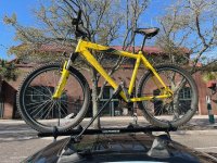
I started down this path a few months ago because I had been harvesting lithium packs from recycling as I was building an 18650 power wall. I didn’t like not using these high current cells for such a plebeian task, and I learned how to fix many of the Ryobi 40V packs. I gave some away, sold some, and wondered what to do since I have 0 Ryobi tools. I decided making my old cheap Diamondback Outlook into a budget commuting machine would be ideal. This Amazon kit (JAUOPAY 36V 750W)https://www.amazon.com/dp/B097YWYK48?ref=ppx_pop_mob_ap_share, a random Pedago rear rack, a couple Terrafirma adaptors, a little Lowes hardware and I was rolling! 1 ride and I was hooked, and suddenly my build that I had under $250 into I was willing to invest in a bit more.
Those adaptors proved to be poor choices for a high-vibration setting and I kept having to adjust how they were mounted, getting bulkier and less rapid for swapping. So I went and built my own pack out of 20700s that I had laying around from Dyson packs. 10S3P, with a (whoops!) Daly BMS and now my rack got the ubiquitous milk crate addition, with the battery under the top tube of my frame. I pulled a headlight off a discarded HiBoy S2 scooter I found next to a dumpster. The controller has a direct pack voltage line from the pack that is switched. Awesome! Wait, that light totally sucked. It made me visible, but was not useful for night riding over 10mph.
I found that I could make my commute (16 miles each way, able to charge) on 2 of the Ryobi 40V 6Ah packs. My DIY pack was 7.5Ah, and good for about 11 miles. I set about designing a pack of recovered 25R cells that was 10S5P, and should be about 12.5Ah. I found a frame bag that would hold this nicely. Then Methods had to go and show how the Daly BMS weren’t good, and down the rabbit hole of opening different BMS I went. Then I decided to crack open the controller and see if the 36/48V sticker was for real, or a hard limit of 48V. Much to my pleasant surprise it was full of 60V and higher rated components! On went a “56V” (14S) Ego pack and the rush for more speed was on.
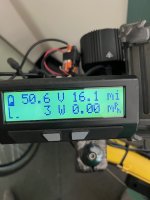
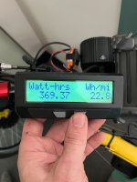
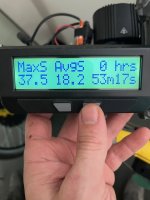
Being able to hit 30mph on the fresh pack was awesome. With the chainring I have, I can’t contribute above 25mph, and more realistically 20-22mph. My commute is often on busy roads for a short distance between the paths and neighborhoods I can route into. This speed makes for a much safer and more relaxing ride (but drivers here have no idea about bikes; we are rare). I am now rebuilding my 25R pack into 14S4P (9.5Ah), debating making some kind of custom mount to hold more (I have hundreds of 20R cells), and finding a box to fit my controller and wiring. I also put more into a CA and SPL-01 from Grin than I spent on my whole starter kit. Totally worth it to have a real headlight for the dark commuting, and to be able to track my Wh/Mi and speed.
If anyone has insight on figuring out the generic controller wiring to fit into the CA shunt that would be super helpful. I get about 25Wh/Mi on the 52V pack, and 20Wh/Mi on 36V. This is because I can contribute by pedaling all the time on 36V, and acceleration is much more gradual. The controller never pulls more than 20A, so the peak is 1000W on 52V and only 750W on 36V. Debating keeping some 36V packs for distance rides, but it’s hard to not have that speed. I think installing the pedal cadence sensor and getting the CA hooked into the throttle will help with that.
I used to work where I could ride a bike 2 miles to the bus stop, take the bus downtown, and ride a last mile to work. All bike path or college area streets where bikes were normal. Now I have 16 miles on heavy trafficked roads. During rush hour, it only takes me 10 more minutes to bike than to drive. I arrive in a much better mood, am helping the earth, and getting that wonderful smug feeling of building something myself that actually works in a useful way. The issues are when I need to suddenly leave to get a kid, or when the weather turns sour. I will not be able to bike commute full-time for now, but the 2-4 days a week I can are amazing! (Also, I really need to upgrade my brakes, and maybe my saddle, and front fork, and install my fenders....) The only downsides are how heavy the bike is, keeping an extra bike around, and wearing out the crotch in my pants.
Thanks for reading!


