Throttle Behavior

Rassy said:
Here are some mini taps for small wires. May be too large for the wires we are working with:
https://www.crutchfield.com/S-vkLakULdBwn/p_669PP644/Posi-Products-Wire-Connectors.html

Those look too big, but the screw tightening idea is cool.

I've used barrier terminal blocks before. They make some fairly small ones. But space is really tight around the controller.

When I install mine, I will solder the wires.
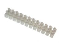
Terminal Block.jpg
 
Okay! Repaired the broken throttle sense wire, sealed everything up, adjusted the resistor (No place left to test it, but based on earlier tests should be in the neighborhood of 20K ohm's), and took a short road test. Everything seems to work just like the older BBS02A and B controllers worked. If I lost any full throttle speed it's not enough to bother me. Can still do 20 MPH in fifth gear and I have top speed set at 20 MPH anyway.

So the fechter fix is successful!

This is a link to a new thread that I posted that explains the problem and the fix in the first post without having to hunt through multiple pages:

http://www.endless-sphere.com/forums/viewtopic.php?f=28&t=93977&p=1375813&sid=1ba2675afbcf9f5094b1027fbdfb0bc3#p1375813
 
Awesome! Glad you had time to test it. I will still try the Darlington setup as it will be even simpler if it works.
If the resistance from the wiper to the throttle wire is 20k or more, it shouldn't affect the throttle top speed.

When I get a chance, I can post the diagrams and pics I have in the new topic.
 
Thanks fechter. I tried to copy that red and orange diagram you posted earlier, but wasn't successful.

My first test was with a Darlington transistor with a straight 100k resistor between it and the throttle wire. Didn't work, put probably will when you use an appropriate resistor. Please post your successful fix on the "DIY Fix" thread and if you do I will point to it in the first post.
 
Hey guys - a fellow (dn9) on the electricbike board came up with a method that disables the pedal cadence sensor just by changing the parameters - no modifications. He did it to run without a display. I took it and expanded on it an made it into a three level throttle-only control setup.

This really works - just like cutting the gray wire. It doesn't work like the transistor mod or the way it was before they started installing the flawed firmware but if you like how it works by cutting the gray wire and want something simple.....

PAS 0 - I=100%, S= 0%
PAS 1 - I= 50%, S= 72%
PAS 2 - I= 71%, S= 72%
PAS 3 - I=100%, S=100%

PAS designated assist level = 0
Throttle designated assist level = By Display's Command
 
That's good to know.

I don't know where cutting the grey wire came from, but as far as I can tell now, I could have simply unplugged the PAS sensor to get the same effect. Even easier to just tweak the settings.

I'm still waiting to try another version of the transistor fix.
 
AZeBikeGuy said:
If I try one of these "hard" fixes I'll go the supervisor & low VGS(TH) MOSFET route...

I'm pretty sure that one will work, but it has not been tested. Either the 0.9v or 1.0v version of the supervisor chip should work.
 
I get it - I prefer something I can calculate and understand the behavior over temperature and tolerance. The SOT23's are no big deal to solder to even with my old eyes - then again I have access to very nice soldering equipment. As long as the cadence sensor output (grey wire) is open-drain this should be great. The pot into the bipolar is sort of yucky to my sensibilities =]
 
How confident are you that the cadence sensor is open-drain output? Did you measure it by loading with different loads and if so what is the pull-up strength? Is the pull-up at the sensor, the controller or both? Does it pull to 5V?
 
How confident are you that the cadence sensor is open-drain output?

I can't answer your technical questions, but the first thing I did after tapping into the wires was a test where I connected the grey and black PAS sense wires which, as expected, disabled the PAS system with no other issues.
 
AZeBikeGuy said:
How confident are you that the cadence sensor is open-drain output? Did you measure it by loading with different loads and if so what is the pull-up strength? Is the pull-up at the sensor, the controller or both? Does it pull to 5V?

Yes, I measured it. 5v with no load. Drops to 2.5v with a 5k resistor load, so assume pull up is 5k. Pull up is in the controller. Sensor is open collector and pulls to ground. I tried to find a supervisor chip that would work by itself, but no luck.
 
fechter said:
Yes, I measured it. 5v with no load. Drops to 2.5v with a 5k resistor load, so assume pull up is 5k. Pull up is in the controller. Sensor is open collector and pulls to ground. I tried to find a supervisor chip that would work by itself, but no luck.

Awesome, exactly what I was concerned about although by plucking 5V and adding a couple of resistors I have something that won't care about the cadence sensor drive. It follows.

What is the problem with the TPS3839?


Throttle.png
 
AZeBikeGuy said:
What is the problem with the TPS3839?

TPS3839 has an active low, push-pull output. It would work fine to drive a FET gate, but you couldn't use it to disable the PAS signal directly.

If there was a voltage supervisor that had an active high, open drain output, you could use it with no extra parts.

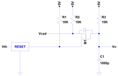
I'm not sure I follow your diagram. What are Vcad and Vo? It looks like it's in series with the PAS sensor line?

Yet another approach would be to use a comparator chip with a 1v reference made with a resistor divider. This would require also using the 5v line (red wire) on the PAS sensor to power it. If the comparator has an open drain output, then it could just tie into the PAS signal line to pull it down.
 
Gotcha!

An open drain reset supervisor would make more sense and with 5V available that shouldn't be hard - plenty use a supply that's different than the one they monitor. I'll take a quick look.

Apologies for not making the nomenclature clear, it was just quick bang it out for simulation.

Vcad is the output from the cadence sensor
Vth is the throttle voltage
Vo is the output to the controller

The idea is that it makes no difference whether the cadence sensor has active pull-up or if open-drain whether the pull-up is on the sensor, the controller or both. It maybe moot since it looks like the sensor is open-drain.

The only fundamental difference with this is that when the throttle is opened it will keep Vo at 5V instead of pulling it to ground. Seems to me that either way should be fine as long as the pulses are interrupted.... but I guess I'll never know until I try =]
 
Use Atmel Attiny25/45/85. 8 pins. Available in a couple of different packages both dip and surface mount.

Program it to read the throttle line with the 0-5V ADC, either pass the PAS signal through it, or just have it short PAS to ground. Use built in RC clock. Use the 5V part, needs only a few mA to operate. Program it to figure out the low throttle voltage automatically when it turns on and clamp the PAS when the throttle is a few percent above that value. About the only other component that would be required is a bypass cap on the power lead. So two very small parts.

http://ww1.microchip.com/downloads/en/DeviceDoc/Atmel-2586-AVR-8-bit-Microcontroller-ATtiny25-ATtiny45-ATtiny85_Datasheet.pdf

If you pass the PAS signal through the chip you could also implement the requirement that pedaling be present to enable the throttle, which is required in some places. In this case if PAS is not present the throttle can be clamped off when the PAS is not present, so the ADC pin would be used as both an analog input and a binary output.

Pins Needed (only 4 or 5 of the 8 available)
+5
Ground
Throttle Input ADC (and throttle output clamp)
PAS Input binary input (for pass through mode)
PAS Output binary output (or use the output to pull down the PAS line)
 
Another one that merits interest is the TPS3808G01. It would require the 5V but it has the detection at 0.4V so you can scale the detection threshold with a divider...
 
AZeBikeGuy said:
Check out the ON NCP303. It's pretty much the same thing as the TPS3839 with an open-drain output...

the open drain version is only available in active low. This seemed to be a common issue with the other manufacturers. Why I added the FET. A 1.0v, active high, open drain part does not seem to exist (in stock), though searching places like Mouser and DigiKey can be challenging and easy to miss something.

The Attiny should work but would need to tap into the 5v supply (easy enough). It seems to work fine to just ground the PAS signal.

The super simple Darlington version is yet to be tested too. This should work and you can adjust the zero throttle voltage point in the Bafang software if the threshold is too high.
 
It would be my intention to either use the MOSFET on the output of the supervisor the way you proposed or the way I came up with last night.

Nice thing is that since it's an open drain output it can be pulled up to 5V making the MOSFET selection easier.

I'd prefer a simple circuit that requires no fussing with (adjusting/programming) over a processor or circuit susceptible to bad drift hand's down. To me a couple of sot23 devices and four or five passives is a very simple circuit...
 
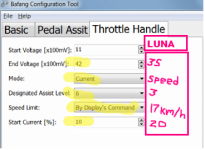
Relating to this problem, but using programming rather than external electronics: I found this in PacoMarkE ' s well documented thread about his BBS02 commuter bike build:
"Throttle. The throttle was acting like an on/off switch instead of a graduated response. I read up a little and changed settings in the controller and I now have graduated control. See the picture below where the pink handwritten values are what was delivered from Luna and the yellow highlights are my current settings. "
bafang bbs throttle settings reccomended.png

Obviously you need the programming cable, drivers etc to make these changes, but might be worth a go. I think that the most important part of this change might be that he changed from "speed" to "current" throttle.
I haven't tried this myself, but when I saw it I thought it looked relevant to this thread so re-posted it.
 
Have any of you probed the cadence sensor output with a sillyscope? If so what's the approximate duty cycle?
 
@Drum, not only have many of us tried all those settings to no avail, all they do is help remove some of the jerkiness by making the controller ramp up to speed slower and such, but he received his kit from LUNA in January of 2017 and the date stamped on his controller shows in one of his pictures and is either 1608 or 1605, very hard to read, but the 160 is clear enough, so his controller was manufactured in 2016 before Bafang made the change we are addressing.

Edit: I researched a bit, and I have had my hands on three controllers from LUNA:
First one on a kit with a date of 1609.... (September 2016), was good;
Second one on a kit with a date of 1705....(May 2017), was bad, and;
Third one, an exchange for the bad one, with a date of 1605.... (May 2016) was good.
 
Yes, I tried everything I could think of with the settings first but this is more than a settings problem. But I can see the settings in handwriting are going to cause problems of their own, especially the throttle start/end voltages. Mine look more like the ones on the left.

I haven't scoped the output of the PAS sensor but based on the type of sensor and magnet configuration, I would guess it's about a 50% duty cycle, just like the hall sensors in a motor. The two sensors are offset to give a quadrature output to sense direction.
 
fechter said:
...I haven't scoped the output of the PAS sensor but based on the type of sensor and magnet configuration, I would guess it's about a 50% duty cycle, just like the hall sensors in a motor. The two sensors are offset to give a quadrature output to sense direction.
Thank you!
 
Back
Top