Timing Adjustment Tool

Could be closed loop. Float the advance at the current draw minima for a given motor rpm, then make the 95%-100% area run a torque maximizing advance.
 
i tougth the 120% trottle was a timing advance i hope this little device board is better to save some current and ready to buy one when the bolt on version is available
i still don't understand nothing but i enjoy the post :lol: :lol: :lol: :lol:
 
I think the optimum advance will be a function of both RPM and motor load (current). At light load you can use more advance. If you took signals for the RPM and current, you might be able to come up with a formula that will calculate the advance. It would still take some dyno testing to find the sweet spots.

I wonder if there may be some other measurable thing that would indicate optimum timing?
 
lifepo4ever said:
i tougth the 120% trottle was a timing advance i hope this little device board is better to save some current and ready to buy one when the bolt on version is available
i still don't understand nothing but i enjoy the post :lol: :lol: :lol: :lol:

I dont believe the infineon controller is capable of applying timing advance. I think the 120% speed setting just scales the throttle signal and removes any small amount of PWM that may be present at WOT. And this accounts for the extra speed that some people have noticed (especially if their throttle output voltage does not quite get high enough).

I am sure Jeremy checked this out in a previous thread somewhere, I will edit in a link to it if I can find it.
Edit: here is the link...
http://endless-sphere.com/forums/viewtopic.php?f=30&t=16728&p=310006&hilit=120+speed#p310006
 
fechter said:
I think the optimum advance will be a function of both RPM and motor load (current). At light load you can use more advance. If you took signals for the RPM and current, you might be able to come up with a formula that will calculate the advance. It would still take some dyno testing to find the sweet spots.

I wonder if there may be some other measurable thing that would indicate optimum timing?


It will be very interesting to check the theories out when we get the right facilities available, I wonder how close the analogies between BLDC motors and IC engines really are when it comes to timing maps?

Time will tell..... :D
 
Burtie said:
lifepo4ever said:
i tougth the 120% trottle was a timing advance i hope this little device board is better to save some current and ready to buy one when the bolt on version is available
i still don't understand nothing but i enjoy the post :lol: :lol: :lol: :lol:

I dont believe the infineon controller is capable of applying timing advance. I think the 120% speed setting just scales the throttle signal and removes any small amount of PWM that may be present at WOT. And this accounts for the extra speed that some people have noticed (especially if their throttle output voltage does not quite get high enough).

I am sure Jeremy checked this out in a previous thread somewhere, I will edit in a link to it if I can find it.


my trottle ouput is at 4.98 volt so its to is maximum i think , but i really feel the difrence when the 120% engage its a nice wot sound :D :D last nigth i was riding at 45 volt and my top speed was 47 kph so its very for me tomorow i will try the 120% troltle with my 100 volt configuration :D :D
 
Burtie, you frickin flower curtain stud! Nice job on the timing board, I have some questions:

How much in parts alone did your board cost?

Is this something that could be preprogrammed for each individual motor and made much cheaper and simpler? It seems only 3 motors are really being used, the Astro, Colossus, and Turnigy. Would there be variations between two same make Colussus, say 21 degrees instead of 22 for optimum power? Is it that sensitive, or would one setting work for all Colossus?

Thanks for your hard work, breakthrough of the year! :twisted:
 
Yeah I was thinking too that the method might be enough, so a dumb adjustment tool with pre-set settings for existing motors might be cheaper/work just fine.

But honestly: how come this idea took so long for someone to think up? =P It's so glaringly obvious now that it is thought up. ;) Good job.
 
Im thinking every motor and every controler will need different settings! So for the small amount of time it takes to find the best timing with no load amps eveyone should set it them selfs!
 
Thanks for the kind words!

Once the 'timing engine' part of the project was cracked, it was not a lot of extra work, or expense, to make the timing parameters configurable.
All these modern micro controller chips already contain harware to support serial communication. The PC interface program, together with the serial comms firmware on the TA would have to be written anyway, so the devices could be configured in the first place. In short, I dont think we would save much by dropping the user configuration options.

I agree with Arlin, that each motor may be slightly different, particularly because the user modifies it by adding hall sensors in one of a variety of different ways.
Different types of controllers may also introduce different amounts of delay, which needs to be compensated for too.

From a production point of view, it is easier to make all the units the same, but give the user the ability to tune it to his/her exact needs.


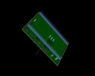
...Talking of production, I have been getting to grips with some PCB design tools over the last few evenings. Turns out it is actually quite fun designing virtual stuff and then being able to spin it all about in 3D :)


Last nights effort.jpg


With the help I am receiving from one or two other members here, we should have some PCBs fairly early on in the new year 8)

Burtie
 
fantastic....count me in for some....
 
Excellent work Burtie! I would like to buy 1 when you have them in sale.

Do I understand well? If motor with fixed halls and running it on 36V system will need X degree advance, same motor running with same controller on 72V will need 2X degree advance? Is efficiency of advancing option, rpm dependent? Linear to rpm?
 
+1 ill take a couple Mr Burtie ;)

Keep up the great work ..

KiM
 
parabellum said:
Excellent work Burtie! I would like to buy 1 when you have them in sale.

Do I understand well? If motor with fixed halls and running it on 36V system will need X degree advance, same motor running with same controller on 72V will need 2X degree advance? Is efficiency of advancing option, rpm dependent? Linear to rpm?

Based on our (toolman2 and me) testing that is perfectly correct. HOWEVER Burtie's timing advance does exactly that. You put in 3 parameters reference rpm, degrees advance and static advance. Reference RPM and degrees advance work together by applying that value advance for every increase in reference rpm. For example if Reference RPM was 1000 and degrees advance was 2 then at 2000rpm you would be 4 advance, at 3000 rpm you would be 6 advance etc.

The static then adds it's advance to the above calculation good for hall misplacement.
 
It seems like there has to be something going on with the phase current or voltage that could be measured to find the optimum timing advance. If this was figured out, it may be possible to have the code automatically adjust and therefore compensate for any kind of motor/gearing setup. Vector control does something like this.

If the timing is too slow (retarded), the current (and therefore the magnetic force) doesn't have time to build up before the pole reaches the optimum spot. If the timing is too advanced, it builds up early and the force fights the forward direction for part of the cycle. It may be possible to detect this condition.

I guess it gets pretty hard when you throw in partial throttle conditions where the PWM is added to the signal. I suspect it is still possible however.

It would be nice to look at the voltage and current waveforms with a dual channel scope while tweaking the timing to see if there's something obvious.
 
I think you're right, Richard. The required advance will be related to the motor time constant, LR which is fixed for each motor but it will also be current (and hence load) dependent to some extent, as well as being just rpm dependent, I'm sure.

Whether or not the timing change with load (current) is important enough to warrant correction I'm not sure. It may be that the rpm effect dominates to such an extent that the extra complexity of doing load timing adjustment might not be worthwhile. If I had to make a WAG, then I'd say that load adjustment might just have the effect of reducing low and part load current consumption slightly, whereas rpm based timing adjustment will be the thing that gives the big performance gain. Some bench testing under different load conditions would soon determine whether this is really the case or not.

Jeremy
 
If I had to guess I would say the rpm is likely around 2 times more important then the load adjustment.
For now the timing curve can be set to what is best for full load and it will still work a whole lot better then now timing adjustment at all!
 
ive just been testing the timing unit on the 120 black turnigy 24magnet motor, and it works perfectly, agian.
so now thats the smaller "hxt" 80-100 turnigy (14 magnet) and the collosus (20 magnet), and now this motor, and with each of them theres been a substantial or sometimes massive reduction in power consumption -at least 20% less power used idleing, or in the collosus case a drop from over 20a to 5.5a.

something i noticed is the major gain is just by having the TA active (even with 0 timing numbers entered) so i would have to assume that the only reason is the way it (very cleverly) takes just one hall signal and calculates perfect 120 deg spacings to feed to the controller?? -any other possible reasons burtie?

there is also further goodnes in this unit, firstly using a reference rpm (say 1000 rpm and 5deg) and applying a proportional advance (10deg at 2000 etc etc) is a really smart move cos the whole problem is controller (and other) lag that is also linear to rpm and is now compensated for with perfection!

secondly you can swap between two maps (named wye and delta) while the motor is running, so its easy to dial in two sets of settings and flick between them at revs, easily spotting the rpm and amps change.. -at the risk of repeating myself, frigging awesome. :D

the above feature could be used for those wanting a different map for light and heavy loads -and to test the difference.
i am also of the belief that these motors are electric not petrol, rpm is THE big player here and load isnt, but the TA will help sort it out either way..

hard to believe but theres nothing that ive seen that i would change from the first test unit, its spot on, perfect.
-all too often theres a heap of wild desires and fantasies being bandied about, that you are not really in a position to fullfill :shock:
so well done keeping it simple and making it actually happen :wink:
 
Awesome. But I have a Hunch load will effect the perfact timing by quite a bit as well! I think of it this way with only 5 amps flowing in the stator as a unloaded current then there is a lot of pwm and it needs a lot of time to energise the stator with the low current, where as with a load it will energise faster because of the smaller amount of pwm. Amonst other things like the fact the once loaded it cant rev up as fast as well.

I am also very excited for this and cant wait to see how it all unfolds.
 
Truly awesome product, My vote for Burtie as "Mad Scientist of the Year!" So it will also work to optimize hall placement positioning, or rather hall sensors that aren't positioned optimally. WOW! This gives everyone who doesn't have a scope the ability to tune hall sensors without moving them? Will you lose some timing ability if this is the case? Put me on the list for one Burtie, these things should be snatched up like hotcakes when they become available.
 
etard said:
Truly awesome product, My vote for Burtie as "Mad Scientist of the Year!" So it will also work to optimize hall placement positioning, or rather hall sensors that aren't positioned optimally. WOW! This gives everyone who doesn't have a scope the ability to tune hall sensors without moving them? Will you lose some timing ability if this is the case? Put me on the list for one Burtie, these things should be snatched up like hotcakes when they become available.
+1... If it comes with an instruction manual, video, ES thread, well something, so I can know how to use it & what it can do. :p :wink:

8)
 
lifepo4ever said:
i hope they can make something for 9c hub motor one day also :D :D :D
If I am reading it correctly it will work with anything with hall sensors!
 
Arlo1 said:
Awesome. But I have a Hunch load will effect the perfect timing by quite a bit as well! I think of it this way with only 5 amps flowing in the stator as a unloaded current then there is a lot of pwm and it needs a lot of time to energise the stator with the low current, where as with a load it will energise faster because of the smaller amount of pwm. Amonst other things like the fact the once loaded it cant rev up as fast as well.

I am also very excited for this and cant wait to see how it all unfolds.

Arlo1
You have to remember that the PWM is turning on and off many times (100's I think) per electrical cycle of the motor. The position of the Halls (either mechanically or electrically) has no effect on how well the PWM turns on and off. The timing can only effect the trapezoidal change event timing out of the controller so I am with toolman2 here (literally and figuratively) I think that RPM would probably be more than 90% of the issue if not 100% of it.
 
Back
Top