Ok I've re-thought this torque arm situation. I want it to be simple. Meaning I can do it with hardware store parts. It also needs to be relatively easy to remove for tire changes (not that it's really an issue with the right precautions)
The main problem for me was derailleur clearance. It dawned on my that if I could spin the axle 90" then it wouldn't be an issue, so I filed my drop outs so that the flats of the axle would be horizontal. And now I have lots of room!
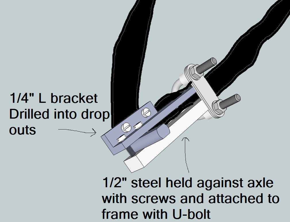
This is about as good as I can come up with. I haven't worked out the actual hardware, but I'm thinking 1/8" width by 1" wide L bracket for the top, and 1/4" steel plating on the bottom. Since they'll be pressed right against the original drop outs and the chain stay protrudes out a bit, the L bracket will have to have the bottom leg removed and both torque arms will have to be trimmed to clear the chain stays.
It will be secured to the drop out with bolts and to the chainstay with a U-bolts. I'll apply the pinch bolts first, and then the U-bolt, and then FINALLY drill into the dropouts. This way the chainstay will see most of the torque, rather than the weaker aluminum drop outs.
John says the big problem with this design is the complete reliance on bolts to produce the pinching force, and I agree. However, it would be easy to modify this quick drawing by using a larger L bracket to incorporate 4 bolts rather than just 2. This would spread the clamping force out along the axle. The devil is in the details, so if any of you have any suggestions I'd love to hear them. I believe this design is solid because it's based on KISS principles. It should work for most bikes, is simple to remove, and is easy to do correctly; All you need to make it is the hardware, a hack saw, and a drill. A tap would be superior than just using nuts, but is not totally necessary.

")