chrisbower
1 µW
- Joined
- Jan 12, 2014
- Messages
- 4
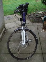
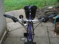
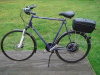
As an old chap, I wanted to convert my Dawes Horizon so that it was comfortable and helped me up hills. Stage 1 of the conversion was to add RST Capa sprung forks and a comfy saddle. Because I was going to add a fairly powerful motor, I also wanted disc brakes on the front - the frame does not have disc lugs so I settled for a "mullet" configuration. Stage 2 was to replace the drop handlebars and move the gearshift levers up from the down tube.
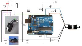
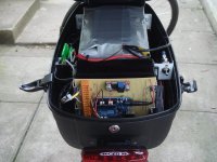
Rather than have a throttle and all the wires associated with it, I opted for a torque sensor in the Bottom Bracket - the Thun X-Cell RT Digital. I used an Arduino microprocessor to read the sensor output, calculate the throttle setting and look after motor braking. Here is the circuit:
I bought a pannier to sit on the rear carrier and ran the wires to it. I brought the Thun wire out halfway up the seat tube and ran the motor wire up the seat stay into the pannier.
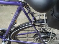
The resulting bike has quite a HEAVY rear end (29kg at the wheel) but no worse than a fully loaded child seat. The range is good because it only kicks in when I need help and then it beats all the Lycra-clad "professionals" up hill...
For anyone interested in building a torque-controlled bike, I have attached the Arduino code below:
Code updated to give a smooth reduction in damping 22 Feb


Rather than have a throttle and all the wires associated with it, I opted for a torque sensor in the Bottom Bracket - the Thun X-Cell RT Digital. I used an Arduino microprocessor to read the sensor output, calculate the throttle setting and look after motor braking. Here is the circuit:

I bought a pannier to sit on the rear carrier and ran the wires to it. I brought the Thun wire out halfway up the seat tube and ran the motor wire up the seat stay into the pannier.


The resulting bike has quite a HEAVY rear end (29kg at the wheel) but no worse than a fully loaded child seat. The range is good because it only kicks in when I need help and then it beats all the Lycra-clad "professionals" up hill...

For anyone interested in building a torque-controlled bike, I have attached the Arduino code below:
Code:
/*
 * Capture the Thun X-Cell RT (digital) output and drive a controller through the throttle input.
 * Program designed to run on Arduino Uno R3 but any Arduino will be OK - just reassign pins.
 * Uses same 9V supply as the Thun torque sensor.  I used a cheap DC-DC converter from eBay.
 * Chris Bower 22 February 2014
 * The concept is an enhanced cycling experience with minimum modifications to the bike.
 * Thun sensor detects need for assistance and motor controller is commanded to provide it.
 * Motor braking is achieved by backpedalling.
 * Key variables are:
 * aveTorque which is created in the interrupt subroutine and is the value obtained from
 *   the last revolution of the Thun X-Cell RT digital; and
 * torqueValue which is calculated in the loop routine and used to obtain the throttle value.
 */
// define constants
const int sinePin = 2; //Int 0 - Brown sine lead + 4.7k pull up to Arduino 5V
const int throttlePin = 3; // PWM output to controller - 4.7k pull-up + 2.2k into 2.2uF
const int brakePin = 5; // Brake signal to controller (Open Collector output)
const int cosinePin =6; //Blue cosine lead + 4.7k pullup
const int ledPin = 13; //Built in LED pin (could be used to work a brake light)
const int torquePin = A0; // grey torque lead - 10nf to ground to reduce stray transients
// define empirically discovered values (yours may be different)
const int zeroNm = 506; // Zero Nm
const int startSlope = zeroNm+15; //lowest value at which motor will assist
const int endSlope = zeroNm+45; //value at which motor will work flat out
const int lowThrottle = 87; //= 1.40V at the throttle output (motor not quite starting)
const int highThrottle = 225; //= 3.62V at the throttle output (max output of redundant Hall-effect throttle)
const int offThrottle =66; //= 0.87V at the throttle output (min output of Hall-effect throttle)
const int startTurns =80; // 5 turns of start ramp-up
// define variables
volatile int pedalIndex; // array pointer
volatile int pulseCount; // if 8 forward pulses, start motor
volatile int backPedal; // if 3 backpedal pulses, stop motor
volatile int stopLight; // stores the "stopped" state
volatile int pedalTorque; // torquePin reading
volatile int pedalArray[16]; // torque readings for 360 degree crank turn
volatile int throttle; // value that gets written to the throttle pin
volatile float torqueValue; // Historic torque value
volatile float aveTorque; // average torque for last crank revolution
//
void setup()
{
  // first stop motor
  pinMode(throttlePin,OUTPUT);
  throttle = offThrottle;
  analogWrite(throttlePin, throttle); //stop motor
  // turn on brake light
  pinMode(ledPin, OUTPUT);
  digitalWrite(ledPin, HIGH);
  stopLight=1;
  // set motor brake on
  pinMode(brakePin, OUTPUT);
  digitalWrite(brakePin, LOW);
  // set to read torque pin
  pinMode(torquePin, INPUT);
  torqueValue=float(zeroNm);
  aveTorque=float(zeroNm);
  // set up cosine to sense backpedal pulse count
  pinMode(cosinePin, INPUT);
  backPedal = 0;
  // set up the sine pulse
  pinMode(sinePin, INPUT);
  pulseCount = 0;
  attachInterrupt(0, intSvc, CHANGE); //when sine pulse switches, execute interrupt service routine
}
//
void loop()
{
  //
  // Average torque for the previous revolution is in aveTorque
  // Here we decide what to do and what throttle setting to output.
  //
  // case 1: stopped - wait for pedals to move
  //
  if (stopLight == 1)
  {
    digitalWrite(ledPin, HIGH); //turn on brake light
    digitalWrite(brakePin, LOW); //brake motor
    throttle = offThrottle; //turn off motor
  }
  //
  // case 2: backpedal detected - turn on the stop light and brake the motor
  //
  else if (backPedal > 3)
  {
    digitalWrite(ledPin, HIGH); //turn on brake light
    digitalWrite(brakePin, LOW); //brake motor
    throttle = offThrottle; //turn off motor
    stopLight = 1; //await forward pedal movement
    pulseCount =0;
    torqueValue=float(zeroNm);
  }
  //
  // case 3: set value for throttle based upon average torque from last revolution and past history
  //
  else
  {
    digitalWrite(ledPin, LOW); //turn off brake light
    digitalWrite(brakePin, HIGH); //turn off motor brake
    // damp response a lot when starting and then reduce damping over the first 5 turns
    torqueValue = ((209.0-float(pulseCount*2))*torqueValue + aveTorque)/(210.0 - float(pulseCount*2));
    if(torqueValue <= float(startSlope)) throttle = lowThrottle;
    else if (torqueValue >= float(endSlope)) throttle = highThrottle;
    // linear power curve
    else throttle = int(float(highThrottle-lowThrottle) * ((torqueValue-float(startSlope))/float(endSlope-startSlope))) + lowThrottle;
    aveTorque = (aveTorque*49.0 + float(zeroNm))/50.0; //reduce aveTorque if not refreshed
  }
  // write throttle value to motor controller
  analogWrite(throttlePin,throttle);
  delay(20);
  // and return to top of loop
}
//
// Interrupt service routine
//
void intSvc()
{
  //
  // if rider backpedals 1/4 turn, turn off motor
  //
  if(digitalRead(cosinePin) != digitalRead(sinePin))
  {
    backPedal = backPedal + 1;
  }
  //
  // if rider starts to forward pedal, count pulses
  //
  else if(pulseCount < 8)
  {
    pulseCount = pulseCount + 1;
  }
  //
  // if rider has forward pedalled 1/2 turn, start motor
  //
  else if (pulseCount == 8)
  {
    stopLight = 0;  //turn off the brake light
    backPedal = 0;  //we are forward pedalling - reset backpedal count
    pedalIndex = 0;  //start collecting torque readings
    aveTorque = float(zeroNm);  //reset average torque to zero
    pulseCount = pulseCount +1;
    for (int i=0; i<16; i++)
    {
      pedalArray[i] = zeroNm;//and clear the pedal array
    }
  }
  //
  // now start collecting average torque readings.  They vary either
  // side of 0Nm depending on whether the left or right pedal is being pushed
  // so normalise them to +ve torque readings
  //
  else
  {
    backPedal=0; //we are forward pedalling - reset backpedal count
    pedalTorque = analogRead(torquePin); //read torque value
    if (pedalTorque < zeroNm) pedalTorque = 2*zeroNm - pedalTorque; // normalise
    pedalArray[pedalIndex] = pedalTorque;// and put it in the array
    pedalIndex = pedalIndex + 1;
    if (pedalIndex  > 15) pedalIndex = 0;//array is circular
    if (pulseCount < startTurns) pulseCount=pulseCount+1;
    //calculate the average torque for 1 revolution
    aveTorque = 0.0;
    for (int i=0; i<16; i++)
    {
      aveTorque = aveTorque + float(pedalArray[i]);
    }
    aveTorque = aveTorque/16.0;
  }
}
//
// end
//
