Understanding and Using EGO Power+ Batteries

FLoHIO117 said:
Has anyone figured out a good and reliable mount design? I'm wanting to use these batteries on my razor dirt bikes and go karts that I've already modified for more power.

If anyone makes them I'd love to buy a couple.

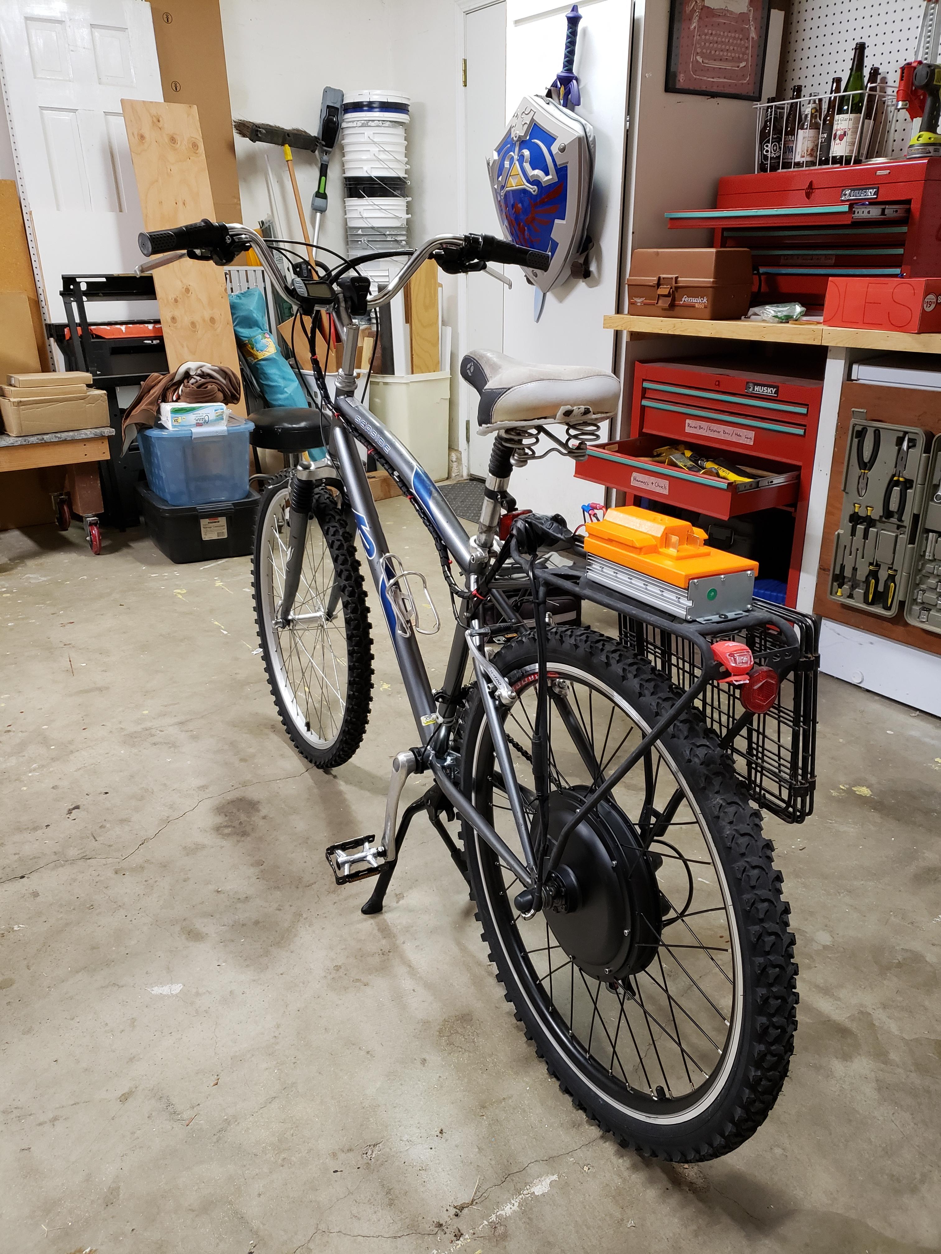
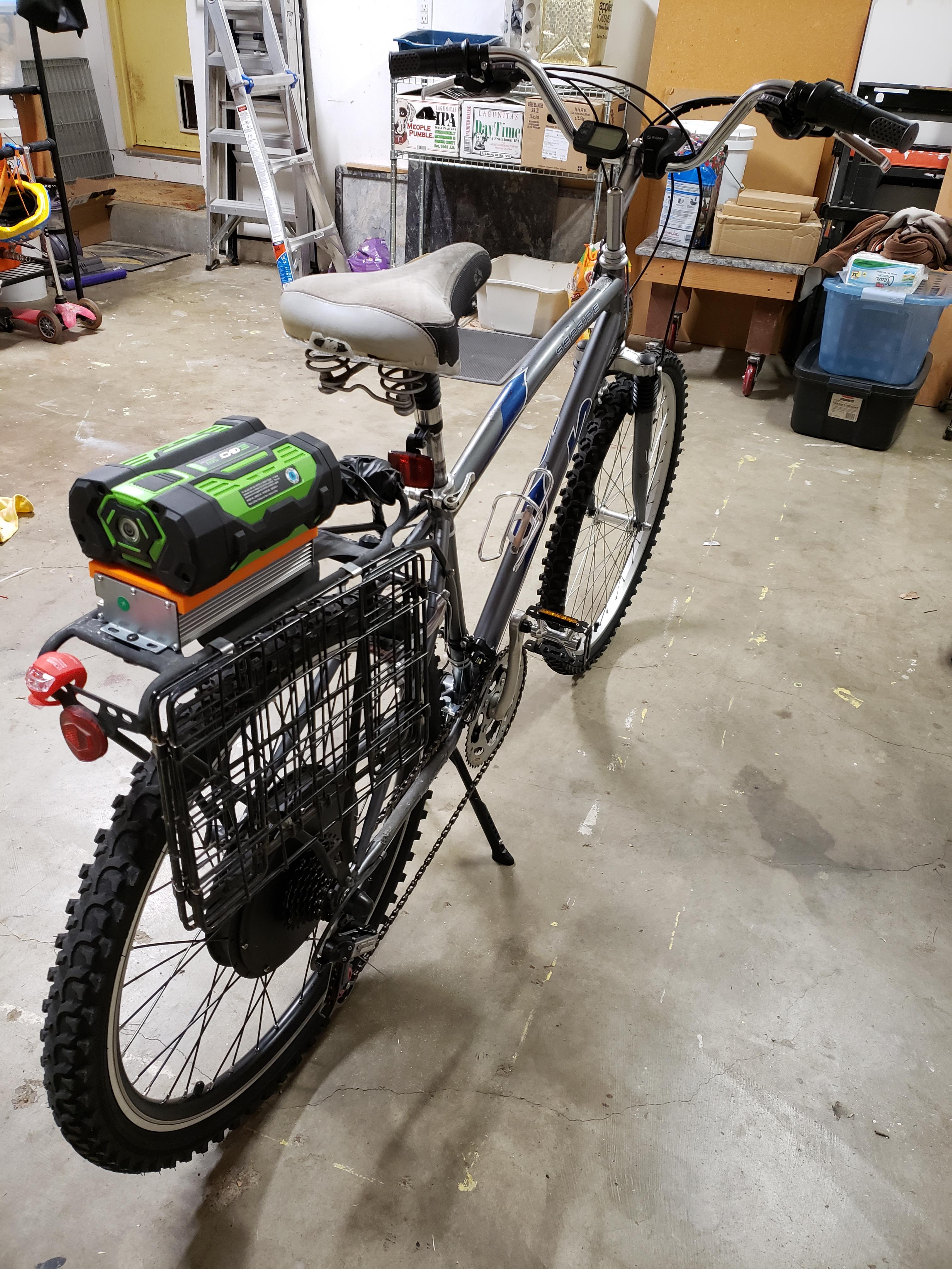
See my previous post with a link to one on ebay
 
CarlRich said:
Anyone still working on this?
I'd like to be able to mount the EGO battery quick and easy but believe I can't just attach to the two outside connectors on the battery. I believe I need to attach somehow to the T or the D connecting port in addition or battery will not work. Yes/no? Perhaps an easier solution is what I found in another thread here on Endless Sphere where guys have simply opened up the case, soldered new red/black wires to the main power lines inside then running these new red/black wires out new holes on back end of battery case. This way you can use it on your bike yet still charge with stock charger. One downside is Downside might be that this bypasses batteries circuitry though I don't know if the battery circuitry analyzes individual cells for either min voltage or over current protection during discharge so may not matter. I'm guessing that during charging the cells are monitored and all brought to full charge. My controllers will shut it down at 42v and prevent over current.

Has anyone been using their Ego charger to charge other 52V batteries? Does the charger require input from the T and D tabs?
 
One of my EGO 2.5 amp hour 56 volt batteries was working a few days ago on the hedge trimmer, and yesterday it did not work. Today I put it in the standard charger and it cycled and did not stay in the charge mode.

I measured the pack voltage around 10 volts, and was not responsive to pushing the button.

I put a small current into the battery of about 60 milliamps, and after a few minutes the voltage was in the low 30's. After that the charger accepted the battery and started charging. I kept watch over it as it charged. I charged it in several short periods when I could watch it.

Before it stopped charging I noticed that the battery LED was flashing once per second. This behavior continued after the battery stopped charging and the charger indicated full.

I removed the battery from the charger and it continues to flash green. I did a brief test in a tool and the battery powered the leaf blower as usual.

This green flash normally indicates the 30 day discharge to storage level. Clearly we don't have 30 days of non-use to trigger that now. I wonder if this is instead an indication that it is balancing, which would be likely after a deep discharge such as this.

Anyone have experience with this?
 
I just got an Ego Nexus generator, and I was wondering if there was a way I could use my 14s packs with it.

https://egopowerplus.com/nexus-portable-power-station/

I'm assuming the generator communicates with the battery, so it may not allow me to just tap into the wiring of an empty battery slot. Worst case is I just have to wire my 52V pack in parallel with one of the batteries right? That shouldn't be a problem during use, and if the 7.5Ah packs use 25r cells, that would be perfect because my batteries use 25r cells, so paralleling them should be no issue at all right?

Any other ideas how I can use my 52V batteries with the generator?
 
Hello, I am new and just stumbled across this thread while I was researching EGO voltage. I thought folks might be interested in the EGO mount I designed (based on the OneWheel design mentioned by a previous post) for my AW conversion kit: https://www.thingiverse.com/thing:3916164. Here are a couple pictures:

PaDOZC9.jpg


YLO91FC.jpg
 
Alan B said:
Did you figure out a way to decode the BMS signal from the battery? So if a cell group goes low you'll know it before damaging the battery?

No, I haven't tried to figure that out, although it would be a good project. I wouldn't even know where to begin to try to figure out how to decode that data signal. I have just been exercising caution. :)
 
Alan B said:
What plastic did you use for printing the mount?

Sorry for the delay in response. I just used PETG, although I think TPU might "grip" the battery better. I usually wrap a strap around it for good measure, although the few times I have forgot, I have never had a problem. I only have around 100 miles on it so far.
 
No one reply . In this thred for 3d printing a dual ego pack holder for backpack
I have make it my self
If get 2 x 7.5ah ego packs look the bms looks is 50amp or 60amp. It use a tx 60 plug in the pack.

For 60 amp will each bms spit 30amp each.??

Thank you
 
Hi, I made an ego pack drive bike a year ago for my neighbor and she loves it. I bought a charger on ebay and stripped it mounting only the battery cradle on her rear rack. The tension was never very good and she has always had to use a bungee cord to keep the battery tightly engaged but she is very happy with it anyway. The battery was expensive but I can rest easy knowing that the customer can always go to the Home Depot for warranty and if necessary buy a replacement.
 
Thank you for reply

I have too wait for next year

I think tool packs are updateing from 18650 to 21700 cells We could see new cells ?

Hopeful we will see power ah jump.

Au is hard place to get cells the laws here

I need to look how lower changeing from 4.20 to 4.10 they bms not smart

Thank you all
 
Alan B said:
Nice.

Did you figure out a way to decode the BMS signal from the battery? So if a cell group goes low you'll know it before damaging the battery?

I've been using two 5ah batteries in parallel which seems to work quite well.

I haven't decoded the data signal, but I think it may be a Texas Instrument Battery Fuel Gauge . Which seems to have a lot of documentation.
https://community.egopowerplus.com/...als?topic-reply-list[settings][filter_by]=all

http://www.ti.com/lsds/ti/power-management/battery-fuel-gauge-products.page

And some info that might be useful for hooking up an Arduino.
https://learn.sparkfun.com/tutorials/battery-babysitter-hookup-guide

https://github.com/sparkfun/SparkFun_BQ27441_Arduino_Library

This Arduino library abstracts away all of the low-level I2C communication, so you can easily initialize the fuel gauge then read voltage, state-of-charge, current, power, and capacity. It also implements all of the chip's low-battery, and SoC-change alerts on the GPOUT pin.
 
Jenming said:
I haven't decoded the data signal, but I think it may be a Texas Instrument Battery Fuel Gauge . Which seems to have a lot of documentation.
https://community.egopowerplus.com/...als?topic-reply-list[settings][filter_by]=all

http://www.ti.com/lsds/ti/power-management/battery-fuel-gauge-products.page
A TI BMS is a good guess, especially since they use a 1-wire protocol. However, I don't think it's what's being used in this case, https://www.youtube.com/watch?v=EH0GS0iUzzM shows a few 8-bit microcontrollers, but no QFN parts which most of the TI parts seem to be (Edit: apparently there are a few TSSOP parts). It's a bit difficult to figure this out since the battery BMS is potted.

I've ordered a spare charger and a "for parts" battery to disassemble and am planning to sniff the bus during charging sometime in the next few weeks to try and identify or reverse engineer the protocol.
 
My spare charger arrived along with two "for parts" 2.5Ah batteries.

Now I just need to find the time to scope out the BMS line on the charger with a good battery and to tear down the batteries to investigate the PCB
 
I plan on using the backpack link
https://egopowerplus.com/backpack-link/

But does anyone know what kind of connector it uses? The cord unplugs from the faux battery adapter and I would rather just plug that in instead of creating a mount for the battery and using the adapter
 
JohnHedge said:
My spare charger arrived along with two "for parts" 2.5Ah batteries.

Now I just need to find the time to scope out the BMS line on the charger with a good battery and to tear down the batteries to investigate the PCB

Any progress on understanding the EGO PCB?
 
Also, given this YouTube on the d terminal:

https://youtu.be/H-hggUXgYlU

It's my guess that the d terminal is a sub clock signal between the battery MCU and the tool MCU (or the charger which also has a similar MCU). When you push the battery button, it puts out a 108 khz pulse on the d terminal for a few seconds.
 
I have reverse engineered some messages between my quick charger and 7.5 Ah battery. Used protocol is similar to 1-wire but bit timing is different.

Here is one message from the charger:
Packet 1.png

CRC calculation method is the same as used for 1-wire:
width=8 poly=0x31 init=0x00 refin=true refout=true xorout=0x00 check=0xa1 residue=0x00

The full set of packets when full battery is inserted to charger is the following:
Full battery charging.png

Each messages (except the header messages) consist 72 bits (6 bytes command/query name + 2 data byte + 1 CRC byte). For GET_VM query the battery is answering:
"OUT_VM" + 0x2E + 0xE0. Converting it to 0xE02E is in decimal 57390 mV = 57.390 V.

I haven't had time to decode GET_CM (current?) and GETCG1 (charge level?) value bytes as it would need testing it on different charge levels.
 
Back
Top