docnjoj said:
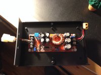
I just got mine and I have a quick question. I know what input and output voltage adjustments are for but it has that 3rd variable resistor that is labeled "CC". Is this for max current ?
Thanks in advance.
otherDoc
It is a current limiter. The instructions suggest setting it low to start. I had completely forgotten about this adjustment because limiting current was not on my agenda. :^)
I'm going to copy/past below, the text file I have that includes all the documentation I found on the booster.
............................................................................................................................
1500W 30A DC-DC Power Converter Boost Module Step-up Constant Power Supply Module 10V-60V to 12V-90V LED Boost Module With Fan
Features:
The power supply module uses double sendust magnets winded with 1.2mm copper wires.
100V/210A low resistance MOS with big power and current input, suitable for big power LED, motors.
Support reverse input protection with MOS so there is no worry about wrong input wire and burn out power supply.
Low voltage protection will protect module and battery against damage from over-discharge when use a storage battery as input.
Thickened heatsink and intelligent temperature control cooling fan dissipate heat better.
Specifications:
Type: Non-isolated step-up module (BOOST)
Input Voltage: DC10V to 60V
Max. Input Current: 30A(input voltage 10V to 30V)
25A(input voltage 31V to 60V)
Quiescent Current: 15mA(will increase when convert 12V to 20V)
Output Voltage: 12V to 90V (adjustable, default is 19V)
Max. Output Current: 20A (related to the input and output voltage difference, the greater voltage difference is, the smaller output current will be. please enhance heat dissipation when current is over 15A)
Constant Current Range: 0.8A to 20A(+/-0.3A)
Reverse Input Protection: Yes (150A MOS)
Lower Voltage Protection: Yes (V8 to 50V adjustable, self-recovery)
Operating Temperature: - 40℃ to +85 ℃(if temperature is too high, please enhance heat dissipation)
Frequency: 150KHz
Conversion Efficiency: 92% to 97% (Efficiency is related to input/output voltage, current and voltage difference. The smaller difference is, the higher efficiency will be)
Input Over-current Protection: Yes (automatically protect when input is more than 35A, and power supply voltage will not increase)
Short Circuit Protection: Yes(input 30A fuse)
Wiring Method: Terminals(please use large current copper wire)
Max. Output Power = Input Voltage*Max Current (If input 12V, the max output power=12V*30A = 360W)
Size:130 x 84 x 52mm / 5.11 x 3.3 x 2.04"
Instruction:
Voltage Adjustment:
Power on module while not connect to load, then adjust "V-ADJ" potentiometer clockwise to increase, counterclockwise to decrease. Due to large output capacitance capacity, response will be slow when adjust high voltage to low voltage.
Current Adjustment:
Adjust "CC A-ADJ" potentiometer counterclockwise about 30 circles to minimize the output current before connecting to load. Then adjust "CC A-ADJ" clockwise to the current value you need.If you use the module for battery charging, connect to output after battery is fully discharged. Because if the more energy is left in battery, the less charging current will be.
Low Input Voltage Protection Adjustment:
If we set a low input voltage protection for a 12V battery, connect input to a 10V voltage, then adjust RV1(clockwise to increase, counterclockwise to decrease) till UVLO light up. Now the protection voltage is 10V, that is to say, when battery voltage drops to 10V, module won't step up voltage and the output voltage will be same as input voltage.
Note:
1. Output wiring can not be reversed or short circuit.
2, If the module is connected to inductive load, the minimum input voltage should be higher(e.g. 24V) and maximum output power should be lower(e.g. 500W).
3, If a storage battery, switch power supply, solar panel or electric generator is used as input power source, the low voltage protection value should be adjusted lower, otherwise it might cause damage.
Package Includes:
1 x Module
................................................................................................................................
The main advantages:
1, dual power sendust 4 1.2MM of copper wire and Rao. 100V / 210A low resistance power MOS, high-power high-current inputs, suitable for high-power LED, motors
2, an input MOS anti-reverse protection, but do not worry about burn out the power input connector
3, low battery protection when the battery input will not be used over discharge damage to the power module and a battery (
5, thick radiator and intelligent temperature-controlled fan cooling.
Voltage Regulation:
In the case of power load regulation output of "V-ADJ" potentiometer (below have indicated) transfer large clockwise, counterclockwise turn down) using a flathead screwdriver, since the output capacitance is large, the output voltage when transferred to a high voltage low voltage reaction will be relatively slow. Built instrument regulating the magnitude smaller. (Default output voltage adjusted to 19V shipping, we adjusted for other voltages, please note or message)
Current Regulation:
Counterclockwise tune "CC A-ADJ" potentiometer 30 laps or so, the output current is set to a minimum, batteries and other connected LED load, clockwise tune "CC A-ADJ" potentiometer to the desired current. After the battery for charging, the battery fully discharged, and then to output, adjust the CC A-ADJ to your current required for charging must use a battery completely discharged before being allowed to adjust, because the battery is remaining the more power, the charging current is smaller. The default output adjusted 3A shipments. For we adjusted the current value of the note or message tone. Do not adjust the current output by way of a short circuit, the circuit structure of the booster module can not be adjusted by way of a short circuit,
.............................................................................................
How does the low battery voltage protection potentiometer work?
Answer: Hi,
Low battery protection, mainly for the input power for the battery to prevent excessive battery, battery voltage is too low, damage to the power module and battery input is switching power supply, also set low voltage protection:
Method 1. Need to have voltage regulating power supply, such as setting 12V battery, low battery protection. A screwdriver is adjusted with RV1 voltage is connected with a 10V power supply module in the input (clockwise voltage adjustable high voltage protection, counter clockwise until the UVLO lights can be reduced), the protection of low voltage battery is 10V, when the battery voltage drops to 10V power module does not rise (input voltage is equal to the output only when the input voltage is higher than the voltage) 10V power boost auto recovery.
Method two: input, connected to the battery or switch power supply, if the board of UVLO lights are out, counter clockwise RV1 potentiometer, the UVLO light tune, light up, and then turn clockwise two laps can be. If the UVLO lamp is lit, a clockwise RV1 potentiometer, the UVLO lights off, tune out then turn two laps. (adapted to 8V-45V voltage) see less
By wangdd22 SELLER on June 2, 2017
..............................................................
Input Low battery protection regulation:
Mainly for low battery protection when the input power to the battery to prevent battery over-discharge, the battery voltage is too low damage to the power module and battery. Such as setting 12V battery low battery protection. Input power module in a termination voltage of 10V RV1 adjusted using a flathead screwdriver (clockwise protection voltage value increase, counterclockwise to reduce voltage protection) until the UVLO lights can, at this low voltage battery protection to 10V, when the battery when the voltage drops to 10V power supply module does not rise (input voltage equal to the output voltage) only after the input voltage is higher than 10V power boost from recovery to start.
.................................................................................