solarbbq2003 said:
novice quetion!:
what is low pass filtering and how are you working out 2.9kHz and 4.8kHz as limits?
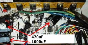
below novice quetion?: if lowering uF of caps in pic above might resolve it would it matter if the caps were surface mount or other?
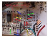
Rkosiorek said - [there is a 2.2K pull up at each of the hall sensors. there is also a 3.3k resistor in series from the hall sensor input to the Cypress chip and a 103 cap from the cypress input pin to ground.]
The LP filter is formed by R-C circuit at the Hall signal input using the LP filter formula:
Freq = 1/ (2 x 3.1416 x C x R ) Hz
.For C = 0.01 uF = 0.01 / 1000000 F ;
and R = 3.3 k ohm = 3300 ohm
Then Freq = 4822 Hz = 4.8 kHz.
If R - (2.2k + 3.3 k) = 5500 ohm, then freq = 2.9 kHz.
Using the rule of thumb (say 10 times), the delay due to 2.9 kHz Lp filter will be negligible if the power frequency is 290 Hz or lower.
If you change 0.01 uF to 0.005 uF, the LP filter will be 5.8 kHz. Then it will not cause any problem if the power frequency is 580 Hz or lower.
It doesn't matter if they are surface-mount type or ordinary wiring type.
However, if it is pre-programmed in the MCU to limit the max power frequency, the change of these caps may not of any help.


 Second to last one I had blew yesterday.