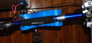
Voicecoils's 2nd build: Giant DH Team

Do they clear your knees?

I found they had to be low, because they are 130mm wide.

On that bike I think I would put one above the downtube, and one below it.
 
Hi Voicecoils,

like mark sais can you pedal comfortably? that is key, i would think that 130mm is doable? you can always get a wider bb and space the pedals out more if the cranks hit.
gaffa tape them in and gor for a pedal ride just to see???
if they work then for sure leave them there!!! tight fit is good, you dont want the packs jumping about so dont worry about that and look at the space you have left in the triangle for the ESC and excess wiring, nice.
unpowered ride with them onboard will tell you all you need to know ;p i reckon if it looks good after a ride box em up 8)


Cheers,

D
 
Hi,

Matt: Thank you very much for the outrunner vs inrunner summary! Great info! Maybe you should copy it to the RC Motor thread.

VC: Sorry to clog your thread. You asked about Neu so I thought it might be good to get information on all of the potential Neu issues.

Its not to scale and I'm sure it would be tight but it looks like Matt's drive might fit between your swing arms (below the top arm and above the lower arm). With the two inch wide version the aluminum tube would probably fit between the swing arms (left of the right arm and right of the left arm). This might gain you an inch or two in terms of the length of the drive unit.
 
Mark_A_W said:
Do they clear your knees?
I found they had to be low, because they are 130mm wide.
On that bike I think I would put one above the downtube, and one below it.

Hi Mark, yes they do clear my knees. I haven't ridden the bike with them resting in there but I did sit on the bike and spin (backwards) and tried the same standing. Here are some relevant dimensions:

downtube width:.........................................61mm
space between driveside crank and downtube:.......57mm
space between non-driveside crank and downtube:..45mm

Total clearence between crankarms:...............~163mm
Battery pack width:...............................125-130mm

dh_batt_clearence.jpg
 
MitchJi said:
VC: Sorry to clog your thread. You asked about Neu so I thought it might be good to get information on all of the potential Neu issues.

Its not to scale and I'm sure it would be tight but it looks like Matt's drive might fit between your swing arms (below the top arm and above the lower arm). With the two inch wide version the aluminum tube would probably fit between the swing arms (left of the right arm and right of the left arm). This might gain you an inch or two in terms of the length of the drive unit.

No worries MitchJi, I do appreciate your contributions :) If good general info on RC drives is posted here people may not see it unless they happen to be following this thread, that's all.

I'm going to try to make a cardboard mockup of Matts drive and see what might work.

file.php

(2nd stage chain drive on disc side)
 
deecanio said:
if they work then for sure leave them there!!! tight fit is good, you dont want the packs jumping about so dont worry about that and look at the space you have left in the triangle for the ESC and excess wiring, nice.

I reckon it just might work and I'm starting to get excited :D
 
So are you going to make a universal triangle box to fit the red bike and this, or separate ones?

Also, how much power are you planning for on this bike?
 
Ben said:
So are you going to make a universal triangle box to fit the red bike and this, or separate ones?

Also, how much power are you planning for on this bike?

Haven't decided yet. If I could come up with a clever method of attaching/detaching the box to the frames then 1 box could work for both. Otherwise, I was thinking of having a permanently attached box on each bike and just have a way to remove one side of each box to slip the batteries in. That way, I could have the controllers etc permanently mounted in each box respectively too. I'm not in a position to have separate packs for both bikes yet.

How much power? I'm told the packs should be good for 40-50 amps each. The packs are 44v each hot off the charger, but at a nominal 3.2v per cell I'm hoping for 3.0-3.8kW of power on tap. I'd like to choose drive components that make the most of the available battery power.

Thanks for checking in Ben :)
 
Abraham, in my experience, under a 30 amp load they will sag to 2.7v per cell after about 6Ah use - and my pack is still new (but broken in).

That's as low as you want to go, so I think 30 amps is a more realistic limit.
 
Hi Mark,

24 cells * 30 A * 2.7v = 1.944 kW :cry:

Hopefully if my cells do have lower internal resistance (from the newer production batch) then perhaps they may perform a bit better.

In the worse case, for the DH Team I could run a set of 12-24 A123 cells in series with the Headway packs to so effectively the motor/controller would pull power from the A123 pack, and the headway pack would charge the A123 pack. This would mean that I could have much greater peak power available for acceleration.

Getting the packs going on the red bike is the first step that will break them in and give me an idea of how much they sag under load. 30A will be the max I will be able to draw on the red bike anyways.
 
Hi VC,

Maybe these clamps will help you. They make three sizes, which I think corresponds to bike tube size( this link is for the XX Large size):
http://www.bicycle-mountain-bike-cycle.co.uk/index.php/product/B125XXL.html

Someone posted (I think Lenk42602) the following about those clamps:
Mt Zefal Makes a cool litttle product called the "gizmo clamp" Which allow one to
mount a water bottle where there are no braze ons. I will be using these slick
little devices to mount the battery case to the frame rather than hose clamps...

I don't think these will work for your batteries but maybe your motor (if they are strong enough?) or something else:
http://www.terracycle.com/Merchant2/merchant.mvc?Screen=CTGY&Store_Code=T&Category_Code=Acmts

Also I don't understand why mounting your motor on the swingarm as shown will interfere with suspension travel. I looks like the motor, rear sprocket, swingarm and wheel will all move together.
 
MitchJi said:
Also I don't understand why mounting your motor on the swingarm as shown will interfere with suspension travel. I looks like the motor, rear sprocket, swingarm and wheel will all move together.

Yes they'll all move together but the concern is, will it smash into the seat tube at full compression? The bike has 8-8.5" travel remember. If I run the rear shock as stiff as possible, I should fine on the road (and it would help with peddling efficiency too) but it would be nice to run the shock nice and plush if I want to take it off road.

Those clamp links look interesting. I've been doing a bit of searching for "two piece collars" and there are some interesting things out there, designed for industrial purposes for clamping onto axles etc.
 
voicecoils said:
Yes they'll all move together but the concern is, will it smash into the seat tube at full compression? The bike has 8-8.5" travel remember. If I run the rear shock as stiff as possible, I should fine on the road (and it would help with peddling efficiency too) but it would be nice to run the shock nice and plush if I want to take it off road.

Those clamp links look interesting. I've been doing a bit of searching for "two piece collars" and there are some interesting things out there, designed for industrial purposes for clamping onto axles etc.
example: 1 1/8" two piece collar

Hi VC,

You might want to consider locating it where it would be if there was a fender and you put it parallel to the fender and slid it toward the back far enough that it can't hit the seat tube. I know I'm repeating myself but you could mount a strong structural fender on the bike for mounting the drive unit.

Good find on the "two piece collar" :!:
 
Hi VC, You might want to consider locating it where it would be if there was a fender and you put it parallel to the fender and slid it toward the back far enough that it can't hit the seat tube. I know I'm repeating myself but you could mount a strong structural fender on the bike for mounting the drive unit. Good find on the "two piece collar" :!:

Yes a big fender/mudguard is a good idea, something I was thinking about for greater stealth and protection from debris. Something can be sorted out for sure.

The collars look like a good (although perhaps quite heavy) way of mounting things to a variety of bicycle tube sizes (as long as they are round).
 
Drivetrain: 2nd stage of reduction
I'm liking the idea of #219 chain, normally used in kart racing, and running at speeds up to 15k RPM in a single reduction.

According to this very useful document: http://www.azusaeng.com/Sprockets/AzSDno219.pdf
I can see that in order to fit a sprocket + chain on the rear wheel with the disc brake caliper and disc in place, the largest sprocket I could use would be a 56 tooth one which has a diameter of 5.634" (5.278" at the root of the teeth). The only problem with this is that I don't believe such a sprocket exists as it would be too small for the 6 hole 5 1/4" bolt circle diameter. The smallest I've seen is 63T which won't clear the disc caliper.

The great thing about the 219 chain/sprockets is the high number of teeth for a given diameter. For comparison, the same 56T sprocket for #35 chain is 6.903". I'd have to go down to a 46t #35 chain to make it fit, which I haven't been able to find any of either.

To make either work, I'd be looking at getting a thin flat adapter made which would bolt along with the disc to the hub's 6 hole disc mount. Then from this adapter the sprocket would be bolted and spaced out away from the disc enough for chain clearance. So from the centre outward would be: sprocket, adapter, disc.

Any ideas guys?
 
Hi VC,

Do these help (it sounds like they would make up whatever sprockets you want)?:
http://motorbicycling.com/f3/top-hat-sprocket-adapter-2131.html

OW I have made the "Top Hat" sprocket adapter which is not only super light (a feathery 2.1 ounces) BUT also allows you to use a disc brake if you so choose! All the advantages of the standard version #1 sprocket hub adapter PLUS super light weight and the ability to retain use of the disc brake system if so equipped.(depending on components used may require the
use of custom spacers below and other "tweaks" since space will be at a premium between the disc and sprocket....may limit sprocket size choices in some cases....again all this is dependent on the frame and components used)...

All pieces are made from the same great aerospace grade 7075 T651 aluminum we make our sprockets from....I have been researching Titanium nuts and bolts but will at first make these adapters available for use with your own nuts and bolts.

Another option would be using one of these belt drives (should be quiet):
http://www.bikeengines.com/index.htm
The first and only geared belt drive bicycle assist engine on the market.
 
MitchJi,

The tophat looked appealing at first, however the 9 whole bolt pattern is not compatible with the 6 hole pattern of #219 kart sprockets.

The BikeEngines belt drive is also appealing at first, however I'm not convinced that mounting to spokes is a smart idea, especially if high torque is a design goal for the finished eBike. The site mentions that belt life can be increased by pedaling from a dead stop before pouring on the throttle which suggests to me that they may also be trying to avoid customer issues with wheelsets and the drive ring wear or failure.

Cheers!
 
Hi VC,

voicecoils said:
MitchJi,

The tophat looked appealing at first, however the 9 whole bolt pattern is not compatible with the 6 hole pattern of #219 kart sprockets.

He makes custom sprockets etc. Maybe he would make what you need.

Cheers![/quote]

I just noticed:
*** Disc brakes (Not recommended):

1. Disk brakes are expensive to maintenance and, because of how they work, put a lot of stress on the spokes w/o motorizing. Braking stress combined with engine torque, puts stress on spokes going and coming.
2. Some disc brakes sit within bike frame, only requiring a washer or nut to space lower strap out, for clearance. Some find the need to grind or file an 1/8" sliver (crescent) from lower strap for brake clearance, others protrude so far beyond the frame of the bike that installation becomes tedious, if not impossible. If possible, we recommend you steer clear of disc brakes.

To check to see if the disk brake would obstruct clearance of Lower Mount Strap - a yardstick is helpful (or something similar).

Place yard stick on top of axle - pivot toward seat then back toward rear of wheel - does any part of the disk brake protrude so far beyond bike frame that it would interfere with the lower strap?
 
MitchJi,

I don't know that he (kingssalesandservice) would be able to retool for a completely different tooth pitch and profile, but I suppose it is possible. I know a place around here which makes custom single speed bike chins 1/2" and 3/16" but again I doubt they'd be interested in the work involved in making the #219 work.

Here's a good site that compares #219 with #35:
http://www.tsracing.com/Techtips/TSchain.html
TWOGEARS.GIF


As for the disc brake comment. I think the excuses for not using one are lame. If you're using a bike with a wide enough tire (large enough contact patch) and want to do any powerful or sustained braking there's no equivalent alternative to hydraulic disc brakes. Look at cars and motorcycles! Hydraulic rim brakes and mechanical disc brakes are both decent and a step above v-brakes/side-pull/canti cable actuated brakes. Instead of him suggesting against them, a better solution to marry the two should be found.
 
I'm sorry, but once you use disc brakes, you never go back. I have no clue why he is against them.

Anyway, the only issue I am struggling with on my mountain bike build (have not started it yet) is rear disc brake with a sprocket big enough to achieve the drive ratio I am looking for.

I may have to mod my Avid cailper and make a "Sproder" (rear sprocket/brake rotor). Either that, or put a small custom rotor on the drive jackshaft. Neither option seems apealing to me, though.

So, how much clearance do you have between the tire and seat post at full suspenison travel?

Matt
 
You might be able to use this spreadsheet to CNC a gear of the size you desire. I found the xls on the web some time ago. Your description sounded like the gear will be going between the disk and the spokes and not between the disk and the dropout. Did I get that correct?

Here is the url to the spreadsheet.
http://www.geocities.com/sidi_steve/NewPix/picView.html

Here is an older copy of the spreadsheet. Hopefully he will fix his link.


Bubba
 
recumpence said:
Anyway, the only issue I am struggling with on my mountain bike build (have not started it yet) is rear disc brake with a sprocket big enough to achieve the drive ratio I am looking for.

I may have to mod my Avid cailper and make a "Sproder" (rear sprocket/brake rotor). Either that, or put a small custom rotor on the drive jackshaft. Neither option seems apealing to me, though.

So, how much clearance do you have between the tire and seat post at full suspenison travel?

Matt

I know a couple battle bot guys who make all the chain sprockets in the bots out of old road signs. Also, according to my dad, one of the old snowcat brands used sprockets that started as a ring of holes and were then cut to the appropriate pitch diameter. Also, looking at bicycle sprockets, tooth shape doesn't look like it matters much roller chain. Anywho, if you get in a pinch I think I could draw up a nice .DXF of a sprocket. Does G-code let you rotate a set of moves around a point and repeat the moves? (I know I can do this on a TRAK 3) Might be able to make a fairly general sprocket cutting G-code program then. One relevant link.

Marty
 
voicecoils said:
MitchJi,
As for the disc brake comment. I think the excuses for not using one are lame. If you're using a bike with a wide enough tire (large enough contact patch) and want to do any powerful or sustained braking there's no equivalent alternative to hydraulic disc brakes. Look at cars and motorcycles! Hydraulic rim brakes and mechanical disc brakes are both decent and a step above v-brakes/side-pull/canti cable actuated brakes. Instead of him suggesting against them, a better solution to marry the two should be found.

Hi VC,

Just to clarify the post on disc brakes was from the site that had the big belt sprocket that mounted on the spokes (Scroll down):
http://www.bikeengines.com/bikerec.htm

I was not suggesting you ditch the disc brakes. I posted that in support of your decision not to use the big belt drive sprocket.

Even if you can get the reduction you want by going directly from a small sprocket on the motor to a large sprocket on the rear it might be too noisy to be satisfactory. Using Matt's unit with the first stage belt drive to reduce the speed of the chain will probably be much quieter.
 
recumpence said:
I'm sorry, but once you use disc brakes, you never go back. I have no clue why he is against them.

Anyway, the only issue I am struggling with on my mountain bike build (have not started it yet) is rear disc brake with a sprocket big enough to achieve the drive ratio I am looking for.

I may have to mod my Avid cailper and make a "Sproder" (rear sprocket/brake rotor). Either that, or put a small custom rotor on the drive jackshaft. Neither option seems apealing to me, though.

So, how much clearance do you have between the tire and seat post at full suspenison travel?

Matt

Everyone,

I'm very near the end of my semester at Uni and am extremely preoccupied trying to get all my end of session assignments and presentations organised. Then I'll have a few days off before final exams begin. In short I'm trying to minimise the time I spend on ebike planning and building for the next month but will then have 3 months off for the summer break. Even so, I can't keep ebike thoughts out of my head! I may check in and see what you guys are up to every once in a while till then.

I'll try to catch up with the other posts later tonight. Thanks for everyone checking in and offering suggestions.

Matt,

The brake/sprocket combined "sproder" is something I've thought about and have seen before. The issue I see is that disc brakes are happy when dry and chain drives are happy when lubricated. The combo is probably not a great compromise but does yield a cool look on choppers.

The only way I can think of to have a decent sized disc brake and a big rear sprocket (or toothed pulley) would be to have a sprocket with quite a complex shape that bolts first to the 6 hole disc mount then kicks back towards the spokes (like the top hat adapter does) and then comes BACK over the whole disc and caliper. Such a sprocket could be machined out of a giant hunk of aluminum, or made with several "rings" with spacers in between.

I'm guessing no one can visualise what I'm talking about :oops: but it is a solution in my mind :D

Lastly, Matt, do you have a good way to measure clearance at maximum compression of the suspension? I can't get much more then my own body weight in compression with the bike not moving and that only really tells me how much "sag" the bike is set up for. Which would be about 20-35" of the overall travel. I guess I could compare clearance with with and without sag, them measure the difference in shock stroke and try to extrapolate out to full travel. But that would assume linear wheel travel and linear behaviour of the shock compression throughout the full travel. Might be a poor approximation.

I might just make a mock up box from your dimensions, tape it to the bike, set the shock as soft as possible, and go outside with it and bounce around and go wild and see if I can bottom out in such a way that I smash the mock up, then reposition or adjust the shock so that I can't. :twisted:
 
Back
Top