Wheel size and torque

Joined
Oct 3, 2018
Messages
53
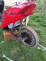
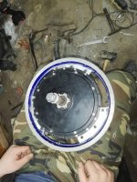
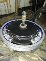
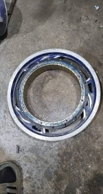
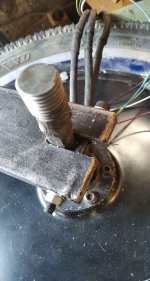
I was having a few experiences with the same hub motor with different rim sizes and I found out the smaller the wheel, the higher the torque, but correct me at any statement if I'm wrong, I'm not an engineer or electrician, it's just my hobby. The efficiency should be better too, because at higher rpms, more power can be delivered without heating up the motor. My first try was a 28 inch wheel, 48V 30A controller with a 300W rated DD hub motor, top speed was 50 km/h with great acceleration. That's what I thought, because I've never tried an ebike before. My second ebike I tried was a 36V 14A one with 18" wheels, it was slower, only 25 km/h, but the torque was way better with less power. So I thought its the way to go, I just need to increase the voltage to increase the speed and power, so I will have insane torque and speed too. I bought a high speed 3kW rated hub motor and laced in a 20" rim. 120V 54A and that thing was both fast and powerful, but the current was too low to reach it's top speed. The 10 AWG phase cables were still warm during hard acceleration at low rpms, so either the voltage is too high or the wheel is still too large. It's a spoked hub motor, but it's impossible to lace in a rim smaller that 20", but I didn't want to decrease the voltage to get better efficiency, because it also decrease the power. I had a 16 inch brushed hub motor wheel, so I cut out the motor and put my 3kW motor without spokes. It looks weird, but it works. And oh my God, the torque. Even 72V 90A beats my pervious 120V 54A 20 inch config, but the power is the same. Top speed was still 68 km/h, so it's fast and very powerful. I applied 120V again and the rear fork didn't like it, the axle twisted, so the cables and my cables and fork are damaged so I have to make a stronger fork plus I have to open up the motor, because the controller throws me hall fault. 120V would give me around 110 km/h top speed, which is still very fast, but I can't put the motor in a smaller wheel.
I know, high speed motor and high voltage is not a good combo a high torque motor in a large wheel could do the same, couldn't it?
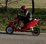
There are some pictures and videos.
https://youtu.be/qIYIvo2FHEo
https://youtu.be/9iO7I3zGIlE
received_164499684720673.png
received_247671203076966.jpeg
received_590446531533450.jpeg
received_771920789996130.jpeg

There's only one question: is the axle connected strong enough to handle all this torque? I'm not worried about smoking the motor, but I'm worried about the axle. It's steel of course, but the stator is aluminium, so they can't be welded together, so they can come loose over time and possibly break the stator. Can that happen?
 
The axles mostly hold up if you aren't jumping like evel knievel, but they aren't the highest quality. 6kw is a reasonable amount of power, not too much.

The bolted aluminum bodies won't come apart, but you can check the fasteners periodically to make sure they are tight.

Yes, smaller wheel gives more thrust, trading off for reduced top speed. Torque at the wheel is directly proportional to the wheel radius.
 
I'm not planning to go off road, and I'm very skinny, so I measured and only 62 kg is applied to the rear wheel which is not too much. The "spokes" came loose at first, but I fastened down again and now they are holding up well. The peak wattage will be 10 kW, but I want to gradually increase the battery current to see how things hold up. It's true that smaller wheel has less top speed, but it can be compensated with the higher voltage, so you will both gain torque and top speed. I could fill the rear wheel with construction foam so it will look better and will be stronger(that's what I did with the front wheel), but it will also insulate the magnets and they will be hot very fast. Too bad that the rim only has 3 aluminium "spokes", so I could only tight it down at 3 spots. I think it will still hold up well, because I had to hammer it a lot to move the rim to it's position, so it took me a while to get there and it was tight even without the bolts. It can only be inserted if you twist the rim first and then twist it back so the holes will match.
received_166456907941832.jpeg
 
the important thing about the axle is that you clamp your dropouts down completely flat against the axle flats.

if they are not flat, the axle will rock or twist in the dropouts, damaging the dropout flats. this further enables more movement, and eventually you get twisting that can either break axles or spin the axles in the dropouts (ripping out your wiring).

use as much surface area mating between them as you possibly can.

that tiny area must transfer all the torque of the motor to the frame, so increasing that area will decrease the load on any specific part of it.

there is a good thread, the torque arm picture thread, that will show you many ways to do these things.


iv'e had all the possible failure modes on one bike or another, in various experiments. they all suck. :( i've welded axles back on to some of them and they still work...but they still suck when they break and you're riding.


the biggest problem is that this type of torque transmission is very poor without precise engineering and good materials, neither of which happens in hubmotors or cheap frames.

stuff that integrates the torque arm into the motor itself, like the old heinzmann, is much better, but there are essentially no cheap generic motors like what you use available with that. the only ones that have this that i know of are the gmac by grin tech, and the grin all axle hub by grin tech.
 
jordanjozsef said:
The "spokes" came loose at first, but I fastened down again and now they are holding up well.

for these, you need to drill holes on both flanges of the motor, so the bolt can go *all the way thru*.

if you do not, there will be strain on the bolts themselves, which they are not designed to take, and they will shear thru. it may take longer now than before, but it will continue to happen. and it will suck when it happens on a ride far from home or a hardware store. :(

what you need is a system that applies "clamping pressure" from the flanges to the part that is left of the old rim "spokes". curved bars of metal that just *barely* fit (like, you literally have to tap them into place with a hammer and wedge) between the spoke flanges and the "spokes", pressed into place further by the bolts that go all the way from one flange to the other. a stack of nuts won't do the same thing; there simply isn't enough surface area.

that would hold them against quite a lot more torque than just the bolts, as the bolts are not designed for that sort of force.

the bolts are supposed to apply pressure that produces clamping (friction) forces between the two surfaces to keep them from moving relative to each other. more surface area means more friction means more clamping means more resistance to torque.
 
jordanjozsef said:
It's steel of course, but the stator is aluminium, so they can't be welded together, so they can come loose over time and possibly break the stator. Can that happen?
yes, it can happen. look up some of doctorbass 's threads for some posts about that, probably a decade ago. but it's rare.

it's also happened where the support arms from the center of the stator where the axle is, sheared thru between there and the outer part where the windings are. also rare.

it's also happened that the stator lamination/winding section rotated on the stator support. if it's only "pinched" together (common in cheap motors), there's not much to stop this, but even so it's still uncommon. if it's actually bolted thru, like at least one of the qsmotors i've seen, it can't do this until it shears the bolt (which shouldn't happen if it's tight and it's clamping the surfaces together).
 
jordanjozsef said:
I was having a few experiences with the same hub motor with different rim sizes and I found out the smaller the wheel, the higher the torque,

No, the torque from any given motor + battery + controller will always be the same. But torque is force * radius, so when you reduce the radius, the force will increase accordingly.
 
The bolts goes through the flanges (m6 bolts), but the smaller bolts (m4) at the spoke holes can't, because the holes are shifted, so I'll have to drill new holes, but I didn't want to ruin the motor. This was just a test wheel to see if the smaller wheel increases acceleration. This will be the final wheel size, so I could make permanent modifications now.

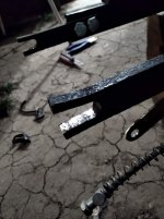
My idea for dropout:
received_214482343159481.jpeg

I think there's no way that it will rip apart.

Here's the previous one:
received_529917931233651.jpeg

They are both 10 mm thick, but the previous one was more narrow as you can see and I found out that the previous motor's axle was 12 mm, but the new ones' is only 10 mm, so it could easily twist in the 12 mm dropout (the cut that you slide the motor in). Plus a was messing around with the reverse function at full throttle, so the axle started to twist back and forth.
I'm still in the testing phase, so I don't go fast yet, if something wants to give up, do it at low speed.

Anyway, you can see that the axle is extended and can be tightened down with M16 nuts. The reason for that is that the axle was too short, so I extended it, but there's no weight applied after extension, only pulling force due to the M16 nut. The original axle carries all the load. I was upset, and tired, it was in the middle of the night, so I couldn't come up with a better idea, but I built up the welding slowly and carefully, and it can be tightened down very well.
 
jordanjozsef said:
The bolts goes through the flanges (m6 bolts), but the smaller bolts (m4) at the spoke holes can't, because the holes are shifted, so I'll have to drill new holes, but I didn't want to ruin the motor.

it won't ruin the motor to drill new holes between teh other ones. i did that to put smaller spoke holes in my mxus3k (450x) motors, so i could use normal bicycle-rim-spokes with them, and they've been perfectly fine on the sb cruiser's rear wheels (the trike, plus me, is about 500lbs. i regularly carry 100lb+ loads, and every month or so 300lb+ loads, sometimes more often, and that's right over those wheels).


I think there's no way that it will rip apart.
i doubt it would "rip apart"...but as i said, the more surface area in contact between the dropout flats and the axle flats, the easier it is on any particular spot of either one.

the less surface area, the harder it is on them. justin_le has a thread specifically about testing this, with contributions and analysis by several people. can't remember the name right now.

if you use regen braking, especially if it is just on/off type, and if you acclerate hard at all, it is going to try to rock the axle back and forth--any, and i mean *any* tiny little gap or unevenness, can allow that to happen, and that will stress the axle (probably at the stress riser area where the thickness changes at the shoulders; this is usually where the axles shear off, like on the qs205 i have here from shortcircuit911). the same thing will happen to a lesser degree with the reverse function.

probably you wont' have issues, but i'd rather point out potential failure points/modes so you can decide what to do, than have you go off unaware and then crash cuz you lost the wheel on the road. ;)


I'm still in the testing phase, so I don't go fast yet, if something wants to give up, do it at low speed.
that's probably not when it will fail. it will usually fail when you are using the most torque, which is when you are riding at higher speeds and then you brake with regen, or when you accelerate from a stop, repeatedly.

so...it'll take a while for a failure to happen, if it's going to, as stresses either bend or fracture things slowly over time. when it does fail, if it fails, it'll probably be a very sudden failure without warning (unless you were examining everything by taking it apart on a regular basis...which itself could cause you problems).


Anyway, you can see that the axle is extended and can be tightened down with M16 nuts. The reason for that is that the axle was too short, so I extended it, but there's no weight applied after extension, only pulling force due to the M16 nut. The original axle carries all the load. I was upset, and tired, it was in the middle of the night, so I couldn't come up with a better idea, but I built up the welding slowly and carefully, and it can be tightened down very well.
i frequently do things when i'm tired...it often results in stuff i later wish i hadn't done. ;)

i don't know what affect that will have on the axle strength, etc. never tried that.

i *have* welded axle ends back onto a broken one, that woudl've otherwise been an unusable motor, and that has gone ok, but it is *very* difficult to get sufficient penetration on such a weld, without applying a *lot* of heat to the whole axle (and thus the bearings, stator and rest of motor) and when you don't get good penetration, the axle breaks in the middle of the weld. probably won't happen on yours becuase as you say it isn't load bearing, but there *is* going to be tension across the weld from the nut pushing on the dropouts (thru a stack of washers or spacer(s), i presume).

one question, though: did you remove all the wiring from the axle (it goes thru a diagonal hole in the axle before coming out either thru or along it) before welding? if not, the insulation could be damaged from teh heat, and potentially short the phase/etc wires to each other or the axle. if it didn't get hot enough to melt the insulation, it should be fine...but if it did, and stayed hot long enough to melt thru it down to teh conductor(s) somewhere along the short length in contact with axle....
 
The new dropout is done, tested with 90A battery amp and 250A phase current. It seems to be okay. I don't use regen, since my final voltage will be 114V (117V when charged), and I couldn't find any controller which supports regen over 90V. So only the reverse could twist the axle to the another direction eventually cause to wear. Anyway the new dropout was so well made, I actually had to hammer the motor into it, it has no play at all when I spun the wheel back and forth when it wasn't tighened down. And I replaced the cables after welding later, but I was very careful not to weld for a long time. The axle and the extension was grinded down to a cone shape and then I built it up, so the center of the axle is welded together too. Riding at high speed causes less stress on the rear fork, because the force is spread due to the high rpm, so I test it at low speed and standstill on full throttle.
 
Back
Top