Would you charge a 4s LiFePo with a "15V" wall wart (intended for charging a 12V SLA)?

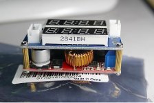
Seems like it would be a lot easier to just trash the original board and get a generic CV-CC regulator board. I've used several of them with good results as long as they are used within their "real" ratings. There are many styles of these, some with displays.

Here's an example:
https://www.ebay.com/itm/Current-Vo...841932?hash=item5d78096c0c:g:mR8AAOSwa0VaE5hu

$3.35 from China. It has an adjustment for voltage and current limit. Also has indicator LEDs to tell you when it's CV (done charging).
Voltage input 5.5-30V. 3A continuous.

 
Fecther what"s the purpose of a 12-volt charger showing 25 volts then going to 15 for a 13.6v charge or 14? volt sla charge ? Is this normal ?
 
fechter said:
Seems like it would be a lot easier to just trash the original board and get a generic CV-CC regulator board....

Something like this one sitting on my desk :)

CCCVmodule.jpg
 
999zip999 said:
Fecther what"s the purpose of a 12-volt charger showing 25 volts then going to 15 for a 13.6v charge or 14? volt sla charge ? Is this normal ?

With no load, it is probably just a measurement artifact. A really cheap transformer with a bridge rectifier feeding a cap will generate the PP voltage on the cap until there is a load, then it will drop to the RMS value.

The CCCV module will work well. You can dial in the current limit so it does not exceed the rating of the transformer.
 
999zip999 said:
Fecther what"s the purpose of a 12-volt charger showing 25 volts then going to 15 for a 13.6v charge or 14? volt sla charge ? Is this normal ?

The wall wart isn't a charger, just a transformer and rectifier. Something like this:

Just as a battery will measure a higher voltage when it carries no load; a transformer will do the same. Ie. The voltage drops once it is connected to something.

The difference between the connect plug voltage and the voltage presented to the battery is down to drops across circuit components.
 
Alan B said:
There are LiFePO4 batteries that are designed for replacing SLA. They internally manage the balancing and the charging limits and are designed for situations like this.

Any pointers/links?

Do you supply the raw rectified supply direct to the pack, or leave the existing SLA charging circuit in-situ?
 
Alan B said:
They are designed to replace SLA, so just swap the battery. They have internal BMS.

BioennoPower has some, A123 now owned by NEC makes at least one model that I've seen. Lots more show up with a search.

Hm. I found this BioennoPower model which has built-in BMS; but ...

1) It states: "Please note that this battery should be charged using a LiFePO4 compatible charger, and not a charger for SLA batteries."

2) There are no numbers on the page or in the pdf stating the under/over volts cutoffs.

Which is worrying because you get others like this which do give numbers, that (IMO) are above and way below what is good for the chemistry:
Code:
1x PCB (7A limited) installed on top 108mm(4.3") x 30mm(1.2") plane to protect the battery from
Overcharge       (>15.6V)                    (**** 3.9V / cell ****)
Over discharge  ( <8.0 V)                    (**** 2.0V / cell ****)
Over drain ( >7 Amp)
Short circuits
1 x 7A polyswitch

3) At $50+$12 (£44) for pack and charger, I can buy 4 SLAs. At ~5years/SLA, that's probably longer than I'll be alive :)

I can get cells to build a 4s 12.8V 4.4aH pack for £12 and an adjustable BMS for £5; which would make a perfect replacement ... but only if I don't have to buy another charger.
 
Some replacements are better than others, some are designed for true lead replacement while others are not. You might have to talk to their engineering directly, I'm pretty sure they were recommending certain models for your use case at a trade show. They often throw in the charger for free with the purchase of a pack anyway. In any case other manufacturer's products do have the appropriate BMS built in. The search I gave you had many to choose from.

Your price calculations indicate that you are looking for a cheap up front cost solution. If you want to design your own pack you will have to deal with the BMS issues. Find a reliable BMS that is designed for SLA replacement use, and rated to charge from SLA chargers (these are not common). It needs to prevent trickle charging and balance the cells to the appropriate LiFePO4 voltages. A failure in the BMS could cause a fire, LiFePO4 cells are robust but they do still burn. Cheap cells might be a concern.

LiFePO4 are not as low in cost as lead batteries initially, their life may be enough longer that they are lower in life cycle cost (10 year life or more in many cases). If you want to minimize up front cost then used/recycled lead is the choice, the flea markets often have these SLA's cheaply as they are pulled off sales shelves after a period of time. All of the LiFePO4 packs I have seen cost more than lead initially, but over the full life cycle may be lower in total cost.

The future cost of lead batteries is unknown, it has doubled over some years already and likely will continue to rise. Lead is being increasingly regulated. So your future cost estimates may be low.
 
I'm sorry I looked I couldn't find that make and the manufacturer of the lifepo4 cell generic blue wrap or A123 lifepo4. Or just a generic Chinese wannabe.
 
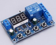
If you put one of these relays between the wallwart and the battery, you can charge you battery with any 12 volt charger.
This relay will stop the charging going into the battery when it reaches the voltage you set. You set the upper and the lower limit. All it does is measure the battery voltage and when battery reaches the upper limit it pulls the relay.
You can have it stop charging at 14.5 volts and restart charging at 13 volts. This small relay handles about 10 amps, but you can have it activate a larger relay , like a 40 amp car relay, or even a 400 amp relay.
I have one connected to my 110ah lifepo4 , which is connected to a solar panel. Its connected 24/7 and works very well. I also use it on my smaller 30ah 11.1 volt li-ion battery, which I charge with either solar or a small 2 amp car battery charger/maintainer that when I put multimeter to it reads 17 volts (a big wall wart).

They cost about 4 dollars on ebay.

Battery Charger Discharger Board Under Voltage Over Voltage Protection Module
a overvoltage relay_2.jpg
 
jonyjoe303 said:
If you put one of these relays between the wallwart and the battery, you can charge you battery with any 12 volt charger.
This relay will stop the charging going into the battery when it reaches the voltage you set. You set the upper and the lower limit. All it does is measure the battery voltage and when battery reaches the upper limit it pulls the relay.
You can have it stop charging at 14.5 volts and restart charging at 13 volts. This small relay handles about 10 amps, but you can have it activate a larger relay , like a 40 amp car relay, or even a 400 amp relay.
I have one connected to my 110ah lifepo4 , which is connected to a solar panel. Its connected 24/7 and works very well. I also use it on my smaller 30ah 11.1 volt li-ion battery, which I charge with either solar or a small 2 amp car battery charger/maintainer that when I put multimeter to it reads 17 volts (a big wall wart).

They cost about 4 dollars on ebay.

Battery Charger Discharger Board Under Voltage Over Voltage Protection Module
a overvoltage relay_2.jpg

Thanks, but the existing circuit board has its own relay -- and srd-s-109dm funnily enough -- and does almost the exact same thing.
 
Alan B said:
Your price calculations indicate that you are looking for a cheap up front cost solution.

My price calculation reflects the reality that a replacement that costs 4 times as much, does not make economic sense.

Alan B said:
The search I gave you had many to choose from.

The search terms you gave me -- as with all of my own attempts -- turns up tons of hits that are mostly too large (10aH.38Ah,56Ah 96ah); of the few that are in the 3-4aH I need, they range from $60 through $300, and that before shipping to the UK; many of their BMSs are non-adjustable 2.0VLVC/3.9V HVC, which is just wrong, or fail to give those numbers in the specs; all of those I've seen so far require a LFP specific charger.

That's why I was hoping for specific links.

Alan B said:
A failure in the BMS could cause a fire, LiFePO4 cells are robust but they do still burn. Cheap cells might be a concern.

What's to prevent a commercial solution's BMS from failing? I get that not all BMSs are equal, and I need to choose wisely, preferably by recommendation.

I see no reason to suppose that NKON would sell poor quality LiFePO4 cells; they come highly recommended, and their wares seemed to be well tested by members here.

If home-built Li packs are always going to be suspect; then there are a lot of people here running risks; but in the end, that's why I started this thread. To find out what the state of play was for constructing a safe and economic alternative.

If the only alternative considered safe is one that is 4 or (many) more times the price, I can pick up a complete replacement portable vacuum cleaner for £10 -- less than teh replacement SLA -- and throw it away in 5 or 6 years. It offends me to do so, but its an economic alternative.

Alan B said:
So your future cost estimates may be low.

I've replaced the SLA twice, and it was cheaper last time than the time before; and the cost now is less (marginally) than last time.
 
fechter said:
In reading more carefully, it seems the circuit board might do the limiting and the wall wart is just a raw supply. It will need some kind of current limiting to avoid overloading the transformer.

Indeed. The buck converter I have allows you to set the constant voltage and limit the max. current. The extra required is something to detect the require SoC and switch it off once it is reached.

The current circuit board uses 12V zeners to detect voltage levels, but appears to only/mostly use them to switch the red/green LEDs. The charging seems to be controlled simply by if the wall-wart is providing more volts than the battery has, the battery takes some charge. Though there may be some hysteresis in the cycle; the board has an SCR on the input from the wall-wart with a capacitor on the gate that may switch the charging on and off to provide non-continuous trickle charging? My simulation of the circuit is as yet imperfect due to a couple of values that I cannot find specs for, and have had to make guesses.

Egs.
What is the inductance value for the relay coil. (This information isn't in the otherwise very comprehensive datasheet for the srd-s109dm :( )
What is the inductance of the primary coil in the wall-wart and what is the turns ratio of the secondary.
(This appears to be critical to the proper operation of the circuit, but I've failed dismally to find any even just typical values for this; nor so far any practical means of discovering it. :( For now I've established values that appear to reflect reality (available measurements) and cause the circuit to operate somewhat close to the real circuit.)

The result is that I have a simulation that works, but is unstable. When simulating the discharge of the SLA to provoke the charge cycle, the simulator will often crap out with "Convergence failure".

Possibly simply because it is a fairly simple simulator. I've downloaded several other free and trail versions but they are either too restrictive -- SCRs only available in the premium version; or only components from a specific manufacturer allowed, which means doing the 'component equivalence' dance -- or are so complicated you need a degree in EE to use them.

That said, I've (re)learnt an awful lot of stuff I either had forgotten, or never knew. So from my perspective, it has actually been an interesting, if at times frustrating, diversion.

What started out as a simple: this SLA is dying fast, I wonder what it would entail to replace it with LiSomething, has turned into something of a quest to understand the circuit, with a view to perhaps modifying it to my purpose.

And this thread -- the original purpose of which was entirely captured by the question in the title -- should have died long ago when the answer (NO) became evident very early on; but each time it has been resurrected -- often by people who haven't read the earlier posts and so come in asking the same question or offering the already rejected solutions -- there has always been some new wrinkle or glimmer of a better or more economic solution.

I have a bazillion questions about the circuit that I'd love to ask of some of you electronics guys, but they are mostly completely off topic for this place. I did take the simulation to an electronic forum to try and get those answers, but they require a certain level of knowledge and understanding and that questions be formulated in the appropriate language (that I don't know), before they will attempt to answer them.

(I think I chose my site badly and clashed with an old-school EE guy who considers the use of simulators akin to hardcore drugs.)

I may try another EE forum, and let this thread finally die the death it has long deserved.

Thanks for your help. Buk.
 
Back
Top