larsb
1 MW
+1 on that! 
BigBlock said:BenBenBen said:Did you have bad feedback concerning that kind of Belt drive first step?
Usually for this application HTD 8M belts work just fine and are easy to find. Take a look to CONTITECH catalogue.
They have several extremely strong heavy duty type.
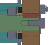
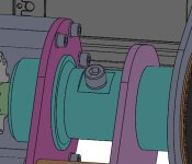
BigBlock said:I would try to go with a slotted design to tension the belt. I'm not a fan of tensioner pulleys. They tend to loose over the time.
Without the pulley you can also end up with a more compact design.
rivvs said:on my bike I used the bac 8000 at 600 phase amp with the 138 90h and a gear ratio of 6.21 :1 And it did not lack low end torque. take a look at my build trhead there is a video.

BenBenBen said:rivvs said:on my bike I used the bac 8000 at 600 phase amp with the 138 90h and a gear ratio of 6.21 :1 And it did not lack low end torque. take a look at my build trhead there is a video.
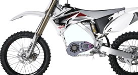
I'll be using this bike mostly for slow Enduro in places with many big rocks, trunks and other stuff that I love to jump on. I'm afraid I would bend it pretty quick... I really don't want to push the bike 2km and make a new custom sprocket every weekend
j bjork said:I wonder if there are any benefit to go with the 90h if you are limiting it with 500pA?
That is if we are talking peak, rms is a different story.
I mean, with just 500pA you might as well go 138 70h v3 and save a lot of work.
But it will be a less interesting build thread :wink:
Im a french canadian actually! I started with 450 amp and it felt slow so Upped the amp until It felt at least as fast as a 250 motocross bike. I was planning to slowly ramp up the amp to see what the motor was capable of but then the battery fire happened.BenBenBen said:rivvs said:on my bike I used the bac 8000 at 600 phase amp with the 138 90h and a gear ratio of 6.21 :1 And it did not lack low end torque. take a look at my build trhead there is a video.
Thanks for sharing experience. Seen your Instagram video link on the RMZ thread, you from France right?
In my case, I don't think I can go so high in phase amp with the Silixcon. 500A will probably be a big max and with good cooling.
What decided me to go with 2 stages is that I really don't want a giant rear sprocket. I'll be using this bike mostly for slow Enduro in places with many big rocks, trunks and other stuff that I love to jump on. I'm afraid I would bend it pretty quick... I really don't want to push the bike 2km and make a new custom sprocket every weekend
OK got it now! Was like "he seems to be French, but nobody afround here waits for snow to melt before going to ride, cause there's just no snow that stays more than 24h..."Im a french canadian