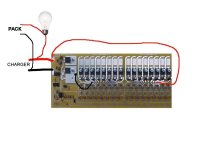
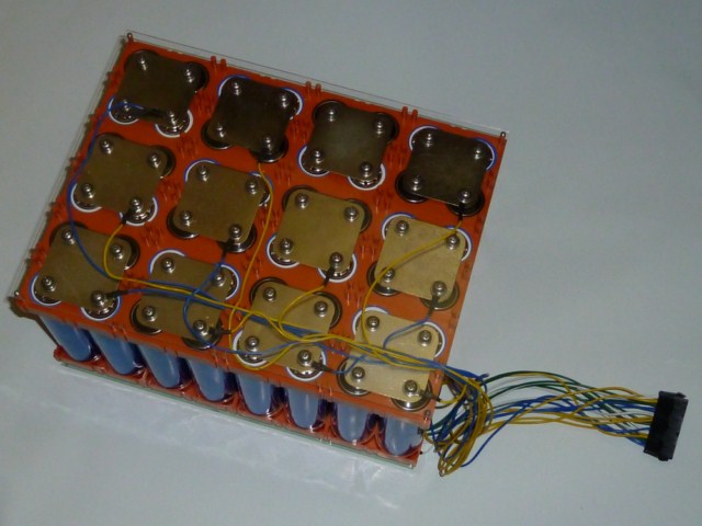
"Zephyr" - Finally, the "v4" Fechter/Goodrum/Hecker BMS...

fechter said:
If you use a very heavy wire and it's not too long, then you could get away with that. Ideally you want to use separate wires directly to the end cells to minimize end cell effect.
The problem with this for me is:
a) I'm going to use a 24-pin molex connector to connector the BMS tap wires to the pack. 24 pins is my lot, here. They don't come in 25-27pin...
b) It looks pretty unelegant to have one extra (say) black wire occupying the first hole of row one in the endplate, but having the first hole of the next two rows (for my 24-cell version) empty due to jump wires being used on the board.

The wire would have to be pretty short anyway, as it would only need to go from the first tap-wire hole to the pack negative about 40mm or so away. Would the ordinary 1mm2(ish) wires - about 18 AWG - that I'm using for my cell tap wires suffice, here, do you think? That's about as thick as will go through the tap-wire holes anyway, from what I can see...

fechter said:
Smaller wire can be fit into the huge holes on the control board. I just strip a little extra on the end and fold it over to make it fatter. Use lots of solder.
Ah! Thanks for the tip :)
 
You can try it and see what the voltages look like. If the end cells are high by more than 50mv or so, you can always add the second wire later. With a very short wire length, it shouldn't be a problem.
 
This is from a Hyperion Charger post, but it's really about the LVC function. (So, I have a question afterwords regarding the LVC setting.)
GGoodrum said:
EBJ said:
another question:

Gary uses an LVC/parallel adapter to parallel his Balance wires. Is this needed? How is this LVC different than a motor-controller lvc?
Perhaps: This "adapter" is acting as a lvc at the cell-state? where as the controller lvc is acting as an lvc at the entire pack state?

Thanks.

Yes, this is so you can have LVC protection at the cell level. This protects against the case where you might end up not as many packs in parallel, for instance, due to a faulty/broken connector. In this sort of situation, the cells will run out quicker than you think, and die before you can do anything about it. Pack level LVC functions are mainly designed for lead acid setups, where the voltage is reduced somewhat uniformly as the capacity is used. Lithium cells are different. Their voltage will stay pretty close to the nominal level all the way until the end, and then it drops quickly (within seconds...). If you don't catch it, the cells can go all the way to zero, which is called cell reversal, and they are dead after that. It is like the voltage drops off a "cliff".

If you have a badly balanced pack, some cells could get down to this "cliff diving" point while the overall pack voltage is still above the controller's pack level LVC trip point. For instance, if you have a 48V controller, and the pack level LVC is set to, say, 40V, you could have the case where 11 cell groups, of a 12s-based LiPo pack, are still at 3.7V but one cell group is at 0V, and still the overall pack voltage will be above the 40V controller LVC trip point.

What the individual cell LVC circuits do is simply monitor the voltage of each cell, or group of paralleled cells, and if the voltage dips too far down (3.0V for LiPo and 2.1V for LiFePO4...), an optocoupled switch is thrown. All of these "switches" are paralleled together and then connected to the throttle signal and ground. The net effect is that if any cell's circuit trips, it will pull down the throttle signal, which cuts the load. This will cause the cell voltage to recover above the cutoff, which resets the circuit and turns off the "switch". If you still are full on the throttle, it will cause the low cell circuit to trip again, which again cuts the throttle. What I've found with a typical 10Ah LiPo pack, and also with 10Ah LiFePO4 setups, is that the first time the LVC trips, it "hits" the throttle, like a big tuna strike. :) If you back off the throttle about halfway, you can go another couple miles, or so, (depends on your usage, of course...), until giving it any throttle at all will cause this hit and recover cycle, which happens at about a 1-2 Hz rate. I've checked the capacity and usually when I get the first "strike", there's about 10% left in the "tank". If I let it go to where any throttle at causes the stuttering, it will take the full capacity of the pack on a charge.

I found it convenient to also include the parallel adapter right on the same board, which simply saves one extra set of wires. Some people make use of it, some people don't. Also, what I offer is a kit, which requires that you solder the parts to the board (3.5 parts per channel...). You can also buy a preassembled LVC-only board from Geoff, in the UK. You'd need to do the parallel adapter separate.

Another option for cell level LVC protection is to use something like a CellLog unit, which has a programmable LVC function which then turns on a buzzer. As long as you can have the CellLogs close enough to hear the buzzer, while you ride, this will work fine.
Hi Gary, great explanations as usual. :) Btw, I'm very pleased you (& your design team) are happy with the latest version & have honored your design by naming it too. It seems you have reached a long awaited milestone, and congratulations is due to all of you! :twisted: :D

Is there any way you can design your LVC for someone to mod the LVC cut-off voltage to be set to a higher voltage, so one could set the LVC to trigger at a higher cut-off threshold? One reason for doing this is so one can have more volts & capacity remaining in the tank to have more return range. The other, main reason, would be for those of us trying to extend the life-cycle of their LiPo batteries. Having the LVC trip at 3.5v for LiPo would be a big advantage, rather than going to the end point of 3.0v for LiPo & nearing its "danger zone" & definitely reducing significantly LiPo lifespan if done too often.

Could this be a "future" design option that could be built-in, so one could simply just order some different parts (or do a simple mod to the existing design) to cause the trip voltage to be triggered at 3.5v vs 3.0v?

Thanks! :mrgreen:
 
There are several ways to do that. Standard TC54 voltages are
1.4 TC54VX14
2.1 TC54VX21
2.7 TC54VX27
2.9 TC54VX29
3.0 TC54VX30
4.2 TC54VX42
4.3 TC54VX43

As you can see, there's a big gap between 3.0v and 4.2v, but there are some alternate parts that might have in between voltages that could work with the existing board layout.

By adding a diode in series with the input, you could raise the voltage by about 0.6v, depending on the diode used. You can also use a resistor divider, but that would add some drain unless you can use the same divider as the HVC.

For low discharge rates, a higher cutoff voltage may be a good thing. At higher rates, there is more voltage sag, so the cutoff voltage will really be higher than the TC54 setting as the voltage will 'bounce back' after the load is removed. With really stiff Lipo cells, there is not as much rebound.
 
I have not been able to access the http://www.tppacks.com/ website for two days. Is it just me?

If I connect 4 packs of 22.2V, 6S, 5Ah to the LVC board, would I then have a total of 88.8V and 20 Ah?

thanks
 
fechter said:
For making this adjustment, I was suggesting the setup below:
Connect the charger to the normal spots on the board, and use jumpers to connect the ends of the cell circuits to the control section. No pack attached. EOC disabled. When you reach the threshold voltage, all the cell LEDs will begin to light up. If your charger doesn't have enough voltage, none of them will light up. You can use the end resistor to attach on the negative side of the cell circuits if it's easier.
file.php

Well I've received my BMSBattery charger, and after many emails to the vendor repeating the same question, I managed to secure details on how to modify the voltage. A pretty digital display on the unit shows the output voltage, and I've lowered it from 87.6V to 86.2V to start my test.

However when I connect it up to the board in the way described, absolutely nothing happens. I think it needs to be under load before it switches on and delivers any power. Does this mean I have to also add the pack for my test? If so could you be very clear in how I do this AND have the power supply at the same time. Are the jumper wires shorting the charger + and - with the ends of the cells still required too?

[EDIT] You say that the LEDs will go from off to fully lit within a narrow voltage range. Any idea of what this range is?
 
do you have a voltmeter? Have you tried measuring whether there is any O/P voltage from the charger?? I think you should ask the vendor/ maker this question. you could also try hooking your battery across it without the BMS and see what happens.
Does the charger have a fuse?? Is there an "ON" light??
 
Gregb said:
do you have a voltmeter? Have you tried measuring whether there is any O/P voltage from the charger?? I think you should ask the vendor/ maker this question. you could also try hooking your battery across it without the BMS and see what happens.
Does the charger have a fuse?? Is there an "ON" light??
The charger looks fine. I tested it already under load.

I covered what I've done so far in my earlier posts and have done the basic tests described to make sure the shunts are giving the right voltage. However this new charger I bought specifically for this pack (an EMC-900) is the kind that only comes on when a load is attached. I was wondering how I could calibrate the charger voltage in the test described above using this kind of charger. It looks to me from the Zephyr instructions that I may have to wire up all the cells first, but I wanted to see if there was another way of doing this.
 
Zenid said:
However when I connect it up to the board in the way described, absolutely nothing happens. I think it needs to be under load before it switches on and delivers any power. Does this mean I have to also add the pack for my test? If so could you be very clear in how I do this AND have the power supply at the same time. Are the jumper wires shorting the charger + and - with the ends of the cells still required too?

[EDIT] You say that the LEDs will go from off to fully lit within a narrow voltage range. Any idea of what this range is?

Sorry for the delay...
Yes, some chargers will not have any output until they 'see' voltage from the pack. This is a safety feature. You can 'bump start' them by applying voltage from the pack. Once the charger turns on, you can disconnect the pack and it should stay on. With the light bulb in place, you could probably leave it connected with no problem. The range from full off to full on will be about 1v.
Zephyr Voltage Adj setup 2.jpg
 
fechter said:
Sorry for the delay...
Yes, some chargers will not have any output until they 'see' voltage from the pack. This is a safety feature. You can 'bump start' them by applying voltage from the pack. Once the charger turns on, you can disconnect the pack and it should stay on. With the light bulb in place, you could probably leave it connected with no problem. The range from full off to full on will be about 1v.
Thanks :)

I did what you said, and attached my crocodile clips from the battery pack to try and 'jump start' it. For some reason it wouldn't play ball when I had the board attached in this configuration (any idea why this might be?) but when I disconnected the charger from the board and attached the pack to it, it jump started it for long enough for me to re-attach the board and then I was able to do the test. I fine-tuned it to somewhere in the region 86.3V, just as it approached 86.4, and this gave me my little orange lights all ever-so-slightly dimly lit.

I was hoping to have my tap wires ready by now, but my doofus vendor sent me the wrong pins for the molex connectors. I hope to have some from another vendor shortly. I take it that it's now just a case of wiring the whole thing up and trying it out properly...
 
I'd guess the light bulb was dropping too much voltage for the charger to kick in. Obviously it would have worked with the bulb out of the circuit, but just wanted to be safe.

Sounds like it's perfectly dialed in now.
 
donorcycle said:
I have not been able to access the http://www.tppacks.com/ website for two days. Is it just me?

I'm sorry about this, but the web hosting company I have used for years, http://www.tokios.com, has either gone under, or they have had some sort of massive failure of some kind. My site, and email server, have both been offline since Tuesday morning. Worse yet, despite my repeated attempts to find out what is going on, I have received zero replies. At this point, I just don't know whatelse to do, but assume it is dead for good. Unfortunately, I don't have a backup, so I'll have to start from scratch. :x

If anybody needs anything, just PM me, and I'll give you a manual quote.

Thanks -- Gary
 
fechter said:
I'd guess the light bulb was dropping too much voltage for the charger to kick in. Obviously it would have worked with the bulb out of the circuit, but just wanted to be safe.
Well that's the thing. Nothing happened with the light bulb, so I tried again leaving the light bulb out of the equation, just tapping the crocodile clips from the battery bank to the + / - positions on the board (where the power supply connectors met the board). The main BMS light came on orange, but charger just wouldn't activate.

Once I detached the charger from the board though, and just attached the pack to the charger directly, the charger came on and stayed on for long enough for me to reattach the charger to the board (pack detached). Any idea why it would have done this? :?

One thought is that my temporary 'jump leads' connecting the banks were a bit dodgy and needed fiddling with to make a proper connection (and get the lights to glow orange). But surely this wouldn't affect the charger, which is after all connected directly to the bank via the board...

[EDIT] False alarm! I tried again, wiring it all up a bit more firmly and the charger came to life the moment I tapped the crocodile clips to the main charger + / - terminals on the board. Still 86.3V, just a teensy bit under 86.4 for the threshold point :)
 
All EMC-XXXX charger from ecity or BMS battery can be bypassed to get voltage present at output :wink:

You just have to install a 10K resistor across the two contact pin of the big relay black inside
( CONTACT PINS.. not coil pins !)

That 10Kohms will take the voltage out of the charger circuit to the output cable and will make it "believe" a battery is present and the relay will activate automaticly.

Caution! : this relay is to protect against too hi or too low voltage of battery according to the set voltage and current you asked ecity to ajust for you. so this protection will be bypassed.


You can also just bypass the two contact of teh relay with a big jumper.. but i like the simple way with a resistor.. it also allow you to trigger the output with a push botton that you connect in serie with that resistor.. so once you push on it, it will toggle the output.

Please note.. you can try lower resistor like .. 1K.. it will work for sure.. but 10K seem to give you a better protection.

Doc
 
Gregb said:
Come on Zenid we are all on tenterhooks..............did it work ????? :oops: :oops: :D :D
Believe my I'm as eager to find out as you are!

So near yet so far. First of all I lost three days because some vendor gave me the wrong pins for my molex ATX 24-pin connectors , now I've run out of wire, so I'm waiting for more so I can do the connectors and wiring on the board side.

Wiring everything up properly is quite a big job, and I'm taking my time doing this properly, soldering all my connections (pins AND ring connectors), and getting the best grades of wire possible so I can welly up the current further with more powerful chargers if needs be.

Here's the finished pack wired into the molex connector. I soldered and heat-shrinked all the connectors to 1mm2 (17 AWG) wiring. I also mounted perspex sheets top and bottom to seal everything in safely. I'll pretty up the wires later with little cable-ties.

pack-640x480.jpg


And here's the finished (populated) board, though as you can see I still have to wire it up permanently.
http://zenid10.files.wordpress.com/2011/06/gfb-st5-16.jpg

As soon as I get my wire through, tomorrow or the day after, I'll finally be able to wire the board up to its molex connector on the other side. But I'm still wondering how to jump wire the banks, and the negative master to the lowest cell negative. I'm thinking maybe just to solder a bit of copper wire or copper braid directly across the tracks to form a circuit on the top of the board.

One think I did notice that made me a bit nervous, is that when I measured my individual cell voltages (this after my experiment where I charged the bank for a while from the ends), two cells were fully charged (almost overcharged), two or three more were at around 3.5V, and the rest had hardly changed from the 3.34V they started out at. Is this difference in charge rates normal, or could it indicate weak cells?
 
That is pretty much what my battery does. It is the reason that we need the balance ccts in the BMS to equalise them all. None of them will be exactly the same at any time so you will always get these differences. the same happens in Lead acid cells but they have the advantage that, within reason, you can keep charging until all cells are charged.
 
Gregb said:
That is pretty much what my battery does. It is the reason that we need the balance ccts in the BMS to equalise them all. None of them will be exactly the same at any time so you will always get these differences. the same happens in Lead acid cells but they have the advantage that, within reason, you can keep charging until all cells are charged.
Thanks for the reassurance! I'll just have to be patient and wait until all my remaining bits arrive...
 
If you don't already have one, I would recommend a cell log from HobbyKing. Very cheap especially the non logging type and very accurate and while you are still wiring up your battery you could include the necessary wiring to provide a charge lead and a permanent monitoring plug for it as well. altho with your set up you would need a few to keep a permanent watch on all them simultaneously. I have an 8S so only need one.
 
Gregb said:
If you don't already have one, I would recommend a cell log from HobbyKing. Very cheap especially the non logging type and very accurate and while you are still wiring up your battery you could include the necessary wiring to provide a charge lead and a permanent monitoring plug for it as well. altho with your set up you would need a few to keep a permanent watch on all them simultaneously. I have an 8S so only need one.
I heard about these and was going to get one (or three). However I can't find any 8s LiFePO4 ones on their site. Do you have a link?

Thanks.
 
Zenid, i think there's only one model because the voltages for the alarm etc are adjustable, according to the spec's, so it should cover lipo, lifepo or others in the adjustable voltage range.

Jim

Edit, / Make that two models, one with logging one without.
 
Right. The CellLog can be programmed for any voltage within its range. No problem with LiFePO4 voltages.
They do suck a fair amount of power, so must be disconnected when not in use.
 
Thanks! They kept talking about LiPo all the time, so I wasn't sure if that they could be used on either.

I have a question about the resistors on the back of the board. I've got them to squeeze into the box nice and snuggly, so that the resistors make good contact. However a few of them got the chalky layer scraped while getting them to go in (some were a tight fit) and I see traces of the bare metal of the resistors exposed in places.

Could this offer the danger of shorting with the box casing, or are the resistor cases fully insulated from whatever it is inside that does the resisting?
 
Back
Top