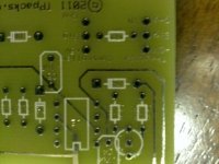
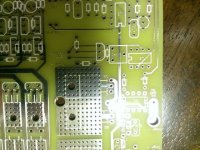
"Zephyr" - Finally, the "v4" Fechter/Goodrum/Hecker BMS...

but that is not what the LVC is for. it is only there to prevent the battery from over discharging by accidentally leaving it connected to the controller as happens all the time.

you use the cycle analyst or other watt meter to keep track of the discharge. most of the people who use a battery on an ebike do not want to have it cut off when accelerating in an emergency. so it is usually kept to an absolute minimum to protect the battery so fully discharged voltage is the level used.
 
dnmun said:
but that is not what the LVC is for. it is only there to prevent the battery from over discharging by accidentally leaving it connected to the controller as happens all the time.

you use the cycle analyst or other watt meter to keep track of the discharge. most of the people who use a battery on an ebike do not want to have it cut off when accelerating in an emergency. so it is usually kept to an absolute minimum to protect the battery so fully discharged voltage is the level used.

I understand that, but this is not for a ebike, even than one could pedal in case of an emergency I guess, actually you only confirmed my choice, my setup will be pretty much always be conected to the pack, and I really do not want voltage to drop below 2.7, the quality of the realforce pouches is supposed to be inferior, in my case the converter should normaly stop the discharge at 47v, it's a continuous 1/2 c discharge from full to 47 v and that's it, some times it may pause/throttle down if the converter gets hot, either way this kits operation does not afect the cars performance at all, it just substitutes gasoline power for electrical power, just a suplement if you will, it's a long story and I don't mean to hyjack the thread. maybe now you may understand my choices.
I guess you have forgotten, this spring you tried to help me understand what I have for bateries, and you would not belive the way my bms was operating, well guess what it was crap, and at the time there were no zephyrs to go arround.
I am working with 80ah blocks if one getts to low the zephyr will be cooking good on the next charge and I'd like to avoid that
I started a thread on the charger, you did mention than about adjusting volts and amps, have a look at that thread see what you make of it.
 
ok so:
BD13616STU wont be available till who knows when but they have BD13616S, I can't tell the difference they both have the same datasheet
299-220-RC same story well they got them if you want 2000 0r more thou that is only $20, but they do have 291-220-RC, again I think they are the same spec, nevermind, 1/4 w twice the physical size, this is going to take a while. 270-220-RC metal film/carbon film does it matter?
299-47-rc I'm stuck 291-47-RC looks promising again 1/4w larger in size

512-FAN431LZXA absolete but hey have 512-KA431AZBU straight legs, 512-FAN431AZXA, 512-KA431AZTA .5% accuracy, almost identical specs, 512-LM431BIZX, they are all similar as far as I can tell would any work instead?
got to work now
 
fechter said:
BD13616S is good.
270-220-RC is good.
Any of the FAN431s will work but avoid the straight legs.

as usual much obliged, that 2.7 tc 54 I was stuck on but digikey had it, they also have some of the discontinued items, I am now cross refrencing both, doublechecking .
one question thou, I believe my packs have jst9 conectors for the balancing leads which look rather thin, I was considering getting a splitter of some sort so I can still run my original bms in parallel, it is good for the display and log capabilities, however I have a feeling those leads may be a little too thin and I may have to redo them, any special tools for jst9 conectors? they look rather flimsy too

would you consider 512-KA431AZTA .5% accuracy, almost identical specs, a fan431, I compared them side by side they look identical but what do I know?
 
512-KA431AZTA is good, just a bit more expensive than the other ones. It has a tighter tolerance.

I don't know about the JST connectors. Some places sell connectors with wires already attached.
Using separate sensing wires for the Zephyr might be a good idea. Otherwise the voltage drop in the original sensing wires will throw the voltage readings off a bit.

Do you have a way to interface the LVC to your inverter? The Zephyr does not have an active cutoff that carries the full discharge load. You need a way to shut down the load when the LVC hits. The inverter should have some kind of interface that does this already.
 
fechter said:
512-KA431AZTA is good, just a bit more expensive than the other ones. It has a tighter tolerance.

I don't know about the JST connectors. Some places sell connectors with wires already attached.
Using separate sensing wires for the Zephyr might be a good idea. Otherwise the voltage drop in the original sensing wires will throw the voltage readings off a bit.

Do you have a way to interface the LVC to your inverter? The Zephyr does not have an active cutoff that carries the full discharge load. You need a way to shut down the load when the LVC hits. The inverter should have some kind of interface that does this already.

I ended up getting

FAN431AZXA , got a bit impatient board is on its way allready, and the name resembled more, and yes come to think of it it's probably best to run separate sensing wires, paralel them at the cell terminals, if I am not mistaking the original ones are bolted to the tabs, besides I am looking at 1 amp bleed current on this version right? I need some heavier gauge anyway.
as for the LVC interface it has crossed my mind but there is so much else I am trying to take in I figured I'll save that for later, the inverter does have some interface I have not yet looked into it but the original BMS shutts it down when first cell reaches lvc which it is set at 2.5v, there is a phone cable and a 2 wire ( jst looking like ) between the original bms and the converter, my money is on the 2 wire, the system is rather geeky in that aspect, but they never got the basics right,

I believe I read about the zephyr having some circuit for a buzzer, I even seen it on a video, one thought I had was to wire some NC relay instead of that buzzer, and the relay's contacts in series with the existing cutoff wire between the original bms and converter, once the system trips it does not automaticaly come back on unless manually reset, which I am fine with, guess I'll cross that bridge when I get there, first I have to have a proper way of charging/balancing that battery, or everything else is dead weight and as far as that goes I honestly do not know of any device capable other than this zephyr, like it has been noted most comercial BMS have 120mA balancing curent on a good day (70mA the one I came across last), what is that going to do on 80ah blocks charged at 15 amp? besides some of these have some weird strategies that don't work, mine has a balancing circuit like that, but the idea was to balance on the bottom at the end of the charge or something like that, turns out it was a disaster and the solution was to disable it, than the bateries got so bad out of wack I don't think the charger ever made it to the CV threshold, cell 16 would trip HVC first I thought it was a dumb charger before I opened it up :lol:

so what ever I have to do to interface it, i'll cross that bridge when I get there, I would have the 2.5v LVC from the original just in case, but what I am really hoping for, if these cells are consistently charged to the same level, every time and they start behaving similarily every time, wich would be a first, the converter will cut off at 47v, long before any of the LVC's trip, I got a constant discharge ( no throttle so no severe sag, in theory I think ), it would be nice to have a charge terminate when the current is too low, and a discharge terminate when pack voltage reaches minimum, that never happened in any of these systems, first one to blow you're done that was their strategy, I got to build a zepher regardless of any interfacing I may have to deal with.
So my board is on its way, components are ordered and all were in stock, digikey had some of those tc54 2.7v and the caps that were discontinued, so for the most part I got the original parts ( I hope ), I got a slightly different Hamond box, the black one was on backorder, and this one description said it's clear ( collor ) I'm curious to see what arrives in the mail.
for what it's worth, to anybody considering this build, my order was just shy of $100, but I did get some doubles ( something to do with custom fit), no wires or nuts and bolts, I have those and they are available locally too, considering the only known comercially available BMS that is supposed to be a direct replacement retails for $555 plus tax shipping .... and there is not much of a description available as to how it works ( probably some weird unreliable ), I believe it has about a tenth 1/10 the balancing capability of a Zephyr, in other words it will never balance that pack ( just make you feel better about blowing cells at least you tried), or I would need 10 of them in paralel to get an initial balance. need I say more, I am not too good or experienced with electronics, that is pretty much obvious, I can build just about anything thou, well see how it goes but as far as I know there just isn't anything comercially available that specs even come close, this is the only way to go.
I was really bumed up this spring to find out they were not available anymore ( read about them years ago ), special thanks to zenid for taking one for the team and keeping those things stocked, I looked for other options all summer, and I was seriously considering building one from scratch if I have to or try to find something close and mod it to work similarly,
as for the Brains behind it, I'm speechless to achieve so much with so little and so simplistic, this last one I like most, I hope I got it in me to see this through, if anything I feel priviledged to have a go at it, speaking of which, whatever happened to Andy?
 
here's a thought :
http://www.mouser.com/Connectors/Pin-Socket-Connectors/_/N-ay0mm?P=1z0wxobZ1yzv2r9&Keyword=9+pin+connector&Ns=Pricing%7c0&FS=True
I think these listings are for both male an female as an assembly.
my particular pack is split in 2 x 24v boxes in series, it is best to get different kinds, so this way it's dumb proof, one pair for each 8s section, should make conecting fairly straight foreward, also it has been mentioned what a bad conection would result, well these don't come apart, this method is common in automotive, I swaped my fair share of engines and for the most part these days in any engine bay there are no 2 conectors alike they can only go back together one way, mater of fact I have a bunch of harnesses I saved over the years, most automotive conectors are weatherproof and they have a safety latch too, these would pretty much eliminate any question of bad connections.

here's a good example: http://www.mouser.com/ProductDetail/EDAC/567-006-000-410/?qs=sGAEpiMZZMs7eK6h2EBtKqX43XSvlyydvlyRHHN3XIk%3d
this is even better, the red tab in the picture is a locking mechanism http://www.mouser.com/ProductDetail/Delphi-FCI-Automotive/54200900/?qs=sGAEpiMZZMs7eK6h2EBtKlXgnLTc5u4k%2fed6%2fgC2W5c%3d,

I opened such connectors that have served 10+ years in a dirty oily moist engine bay, throughout all temperatures imaginable and the contacts were like new.

hope this helps
 
while waiting for my components to be delivered I am looking into connector options, I kindof like the idea of soldering the wires directly to the board and was looking at external plugin conectors,
http://www.mouser.com/Connectors/Pin-Socket-Connectors/_/N-ay0mmZscv7?P=1z0wxob&Ns=Pricing%7c0&FS=True
this is what i foundm question is Where it says in the dsescription, "pin and socket" does that mean both female and male plugs?
there are so many and so cheap too, one could order different kinds so pugging in is pretty much dumbproof, thou Mouser is so confusing, I cant tell which 2 plugsm male/female match, there is no refrence as to which goes with which
 
velias said:
I just used a dremel with a small drill bit and scraped the plating out from the interior walls of the via where it connects the collector trace on the bottom of the board to the emitter trace on the top.
Maybe a xacto knife will work too.
This is a Rev 4.4.2 board so maybe other versions are different and ok
Its on the 8th and 16th channels, so theres a similar via/hole on the 16th channel too.
Basically what is a via should just be a hole or not even there.

Capture1.JPG

I am one happy camper today, Zenid's package was just delivered and I must say boy you sure wraped it good, had to get a knife out , shaking and all excited, thought I was going to brake it in the process :lol:
It is rather larger that I imagined, never paid much atention to the dimensions before, but it does look smaller in pictures and videos, none the less, boy there's a lot of tiny holes and components to go in I can hardly read most of them and I am not that old but I can see how this is not for everybody, I am an avid do it yourselfer the way I see it we al have simmilar brains, 2 hands 2 eyes etc, if you all can develop it I should at least be able to follow instructions and put it together, but I am nervous,
I quoted the post above, my board looks like it has been revised and does not have that issue, I will however post a picture later this evening just to confirm, there is also a spot for a diode labeled D9, I think that was the other add on I read about, I have been reading about this bms on and off for some time just now that I have the boar on hand some of it begins to click.
a preliminary thanks to all involved for making this happen, I hope I got it in me to put it together right and do you proud, either way this goes I am extatic to even have a go at it, I never had any luck with electronics all my previous atemps were in vain ( granted I don't really know what I am doing ), just the other day I had my first ever success modifing a ATX PS, which I do believe I mey need in this process, somewhere in the test instructions I read something about an adjustable PS, up to about 20V I believe, well I got that now
 
fechter said:
Gregb said:
well that's great my board doesn't even have this new R14 position on it. better check yours Zenid. Looks like I will have to cut track and mount on underside of board.

Yours should look like this. If not, tell me the version number.

R14 location is circled in blue


this new layout looks rather different, I could not find either R14 nor R15 looks like the U3 is in a different orientation, I may be overthinking it at this point and I may have read too much some of which has been revised since, but I figured I'd bring it up so I do not loose my thought
 
fechter said:
OK guys, got it.

The problem was with higher charge currents/smaller cells, the on time during cycling was too short for the EOC detector to trigger. In earlier testing, we were mostly using very large cells at a lower charge rate, so the timing was not an issue.

The solution will be to add a 1N914 diode to enable the EOC detector during the HVC delay time. My test setup used no cells (worst case) so the timing cycle was as short as possible.

The diode needs to go from the base of Q2 to U3 pin 7 or the gate of the main FET. The cathode (end with the black band) goes to Q2.

Here is a layout diagram showing the location of the diode (in blue). I think you can bend the legs of the diode around the existing resistor legs and solder it in.

The anode side of the diode can go to either end of R14.

and this I see a spot for the diode on my board looks like this R14, R15 has been eliminated all together but what do I know :?: I ordered one of each just to be safe, now that I have the board in hand apears all those issues have been adressed, should be pretty straightforeward I should not have to drill or scratch anything, I believe the BOM was updated too I was a bit confused by all the moaning, through the 30 pages I guess.

I still have no Idea what schematics you all mention through out this thread, I never came across any, I should be ok I recon, looks like the bugs have been exterminated, we'll see how dumbproof it is now, guinea pig comming up :lol: I got my digikey order just a couple outdated components that mouser did not stock any more, mouser should have been in too, guess it will be tomorow.

Once you install the diode, you should be able to crank the charger voltage up a bit and still get good end of charge shutdown.
Some cycling is normal if there is significant cell imbalance, but it should shut down after a reasonable amount of time. Having the diode will make variations in charger voltage less critical.
 
2007blueprius said:
I am one happy camper today, Zenid's package was just delivered and I must say boy you sure wraped it good, had to get a knife out , shaking and all excited, thought I was going to brake it in the process :lol:
{...}
Congrats! :D Yes, I am a little obsessive about packaging. Better too much than too little, I think.

2007blueprius said:
I quoted the post above, my board looks like it has been revised and does not have that issue, I will however post a picture later this evening just to confirm, there is also a spot for a diode labeled D9, I think that was the other add on I read about, I have been reading about this bms on and off for some time just now that I have the boar on hand some of it begins to click.
Yes, a diode (D9) got added for a fix in this version. I've added it to the BOM, but probably too late for you guys. Richard says of the diode: "diode is a 1N914 or any signal diode. 1N4004 would also work there"

In the BOM it appears as a change in quantity for 1N914 from 3 to 4:
"D5, D6, D8, D9: 1N914 512-1N914T50A 4 512-1N914T50A|4"

Latest BOM is always here: http://www.zenid.com/docs/Zephyr%20LiPo-LiFePO4%20BMS%20BOM-v4.4a.doc

2007blueprius said:
a preliminary thanks to all involved for making this happen, I hope I got it in me to put it together right and do you proud, either way this goes I am extatic to even have a go at it.
Glad to hear it. Have fun! Just take your time and do a really good job soldering the components, and take all the precautions when you test it (like using that light bulb to prevent damaging anything if you have a short). You might consider little sockets for the U2 chips; it makes them easier to replace if you do something silly and blow one (like I did, lol).
 
Gregb said:
well that's great my board doesn't even have this new R14 position on it. better check yours Zenid. Looks like I will have to cut track and mount on underside of board.
The diode mod hasn't gone onto my board yet, - I just keep the voltage not too high too avoid the cutoff issue. Next time I open her up I'll add the new diode and see what a difference it makes.

[EDIT] I tell a lie, I DID make the mod! I just never got round to fiddling with the charger voltage again, so can't say how it improved this. I have my power supply set to 85.6V, rather than the theoretical charge voltage of 86.4V for a 24s LiFePO4, as the 0.9% difference does not make any difference, and to my mind errs on the side of caution.
 
I added a diode to my order also a r14 and r15 which apears are not used anymore, but hey for a few cents I'd rather have them, I also have a electronics supply store within walking distance, it would have probably take me days to pull them off the shelf and end up a bit pricy too, so as long as I got the bulk of it to get me started it will do, as for those chips, I really do not understand what the big deal was, I have a desolder iron, it's nothing more than a rubber bulb atached by a pipe to the tip, and sucks out molten solder, I salvage stuff with it all the time, well whenever I do tinker with this kind of stuff, it was cheap too like $20 maybe, not enough to pay attention anyhow, I hope it will go together flawlessly thou I doubt it especially since I have my hand in it
 
just to clear this up, this one:
WP_20131203_002.jpg
board is labeled r14 diagram is r15 either way both say 1k so 1 k it is than.
the other:
WP_20131203_003.jpg
should be here somewhere, I saw it on previous versions off pin 7 of u3 I think, this board has the diode off that track but I could not find the 100 resistor, now granted I may be a bit blind or maybe it is not needed on this version, the diagram puts in between pin 7 and q3, let me know if I need to make something happen, I'd rather do it now
 
2007blueprius said:
just to clear this up, this one:
View attachment 1
board is labeled r14 diagram is r15 either way both say 1k so 1 k it is than.
Yes. The throttle pass-through resistor (top-right between the two rows of three holes) was called "R15" on my version of the board, but on the 4.4a it's called "R14". No biggie. Probably the software managing the names.
2007blueprius said:
the other:
should be here somewhere, I saw it on previous versions off pin 7 of u3 I think, this board has the diode off that track but I could not find the 100 resistor, now granted I may be a bit blind or maybe it is not needed on this version, the diagram puts in between pin 7 and q3, let me know if I need to make something happen, I'd rather do it now
The design has changed in all sorts of ways from one version to the next. This one is the latest and greatest, so everything should be fine. If you have a specific question, ask and I dare say Richard will chime in when he has time.
 
no big deal either way, my mouser order is not in yet , go figure, so I was kindof going over the board, it's diferent when you actually have it in hand, I figured if anything needs to be done if I can I'd rather do it now.
speaking of which Zenid, what's the big Idea making the 16s endcap a hole short for the tap wires?, I know, I can jump it inside , think I'll drill a hole anyhow since my pack is split into 2 x 8s boxes.
anywho stay in touch, I'll be posting as I go along just to keep my line of thought, I'm sure at this point I am overthinking it, but I am a bit out of my comfort zone, half thse components I have no Idea what they are nor have I had a chance to read about it, even so they are so many try as I might I can not retain any ore new info at this time, I;ll take it a step at a time.
 
2007blueprius said:
no big deal either way, my mouser order is not in yet , go figure, so I was kindof going over the board, it's diferent when you actually have it in hand, I figured if anything needs to be done if I can I'd rather do it now.
speaking of which Zenid, what's the big Idea making the 16s endcap a hole short for the tap wires?, I know, I can jump it inside , think I'll drill a hole anyhow since my pack is split into 2 x 8s boxes.
I asked Richard about this and he didn't know. The hole is there on my version of the board, but one was dropped for this version. I will add it back in for the next release. Strictly speaking - like you say - you don't really need that extra wire, anyway, as the positive of the last circuit of an 8-cell bank can just be connected directly to the first negative of the next 8-cell bank, like I did in my wiring.

gf16d-1600x1200.jpg


gf16c1600x1200.jpg


http://zenid10.wordpress.com/category/4-how-to-guide/4-7-lithium-upgrade/4-7-2-building-the-goodrum-fechter-zephyr-bms/4-7-2-3-wiring-and-assembling-the-zephyr-bms-unit/

Basically, if you wire it the way I did, you don't really need 9 holes per bank, just 8. I plan to add little holes at the elbows of where the 8-cell banks meet ( where I had to drill my holes), so that cross wires can be added more easily for people who want to do it this way. I found that a 24-pin ATX connector was perfect for such an arrangement. I ended up using my extra holes for the lvc wiring instead.
 
I never liked the end holes much and on mine I just made a big slot for all the wires to pass through. The slot is just a cutout on the edge of the end plate so I can remove the end plate without disconnecting any wires.

I wouldn't be surprised to see labeling errors. Use the schematic and just make sure the right parts are going in the right place.
 
fechter said:
I never liked the end holes much and on mine I just made a big slot for all the wires to pass through. The slot is just a cutout on the edge of the end plate so I can remove the end plate without disconnecting any wires.

I wouldn't be surprised to see labeling errors. Use the schematic and just make sure the right parts are going in the right place.

that is actually my question, the schematic you sent me shows an extra 100 ohm resistor between D9 and Q3, the board has a sreaight run, no resistor, I could drill a couple holes and break the run so I can install it but what do I know? I may be reading the schematic wrong or the board for that matter, also from the same pin on Q2, through R6 100k there's a run to pin 2 of U2 on the diagram, on the board it ends up on pin 7 of U2,
I think I am reading those right, and they do not match, maybe I got the wrong diagram?, let me know if I need to take some more pictures, either way, if I can't get past this, good luck testing it, granted I am not at all experienced, I can somwhat follow a circuit, it is possible I am getting something wrong, I'll keep staring at it till I hear back but I believe the diagram is different than the board
 
Let me check on that. I'm on the road and don't have all my files with me. The 100 ohm resistor going to Q3 is not needed. I must have sent the wrong version of schematic earlier.
 
fechter said:
Let me check on that. I'm on the road and don't have all my files with me. The 100 ohm resistor going to Q3 is not needed. I must have sent the wrong version of schematic earlier.

no rush, I just got my mouser order in today, I'm taking my time with this, like I said I am a bit out of my comfort zone that's why I'm doublechecking everything, if you have them, send me the shunt diagram, actually I think I have one from you, I'll crossrefrence it tonight, been playing with some laptop batteries these days killing time, I am a bit nervous about soldering that board, I am ok with batteries, and wiring, I'm better with oxy and silver solder, and those compnents are so small and close together nor am I very patient, plus the via's are made of solder too, not corper like most commercial ones I can already see me burning trough , I might have the wife make this board for me, she's a bit better tempered and patient.
I'll be sorting out through the parts tonite and see which one is which, I have to pull up wiki every time I have to count resistor stripes, black brown red aand I forgot the rest, that is another thing I am nervous about, hope I don't mix them up, I think I'll mock up 1 circuit and post a picture, get it approved before I burn the rest in.
 
The tin plating on the boards makes them very easy to solder. I usually start by stuffing the low-lying parts first, like the resistors and try to do them in rows. Stuff a row, solder, clip, then move on to the next row. Soldering a straight row of wires goes very fast. If you try to stuff too many at the same time, it becomes hard to reach some of the lands. Once all the low-lying parts are installed, move on to the next tallest parts, etc. until finished.

I also found it useful to borrow a muffin tin from the kitchen (the kind that has 12 holes) and label each hole with tape and use that to keep all the raw parts organized while building.
 
OK< hands. up..I have not read all 29 pages of this thread to find the info...and have not been reading it as it progresses.

Two points/ questions:
The sale thread link on page one is broken.

Can these units be used with less than a full compliment of cells...so use a 24s unit for only 20 cells?
 
Back
Top