I've been working on field oriented control with TI eval boards (LAUNCHXL-F28069M and BOOSTXL-DRV8323). The power handling of the driver board is marginal, so I want to monitor the PCB temperature under the FETs and implement protection. Pictures of my first attempt are below, with a TMP36 sensor in a TO-92 package, attached with high-temperature silicon adhesive (GENNEL). It measures temperature, but presumably the reading is some average of air and PCB temperature with unknown weights.
Does anyone want to guess to what degree the reading corresponds to the PCB, or suggest a better method? TIA.
Update: I'll try to calibrate the reading with an IR remote thermometer (stuck in a COVID-19 locked-down office).
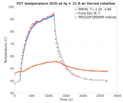
Well, I rescued the IR thermometer to calibrate the TMP36 circuit board sensor. After covering the exposed metal on the FETs with kapton tape for better emissivity, I redid the temperature measurement (see graph). At the peak, the IR thermometer measures about 12 more degrees C than the TMP36. Actual temperature may be even higher, because the IR spot size is probably bigger than the FETs.
I really want to operate up to 35 A in short bursts and power rises quadratically with current, so a serious heatsink would probably be needed. Due to the mechanical design, it seems difficult to pull the heat out of the PCB, which is a drawback of this driver board (BOOSTXL-DRV8323). The electrolytic caps also got hot during the test.
On the graph, current switches on at about 150 s and off around 1150 s. Ambient is 24 deg. C. TMP36 temperature is rescaled to match the IR data. TMS320F28069M is the processor.