DIY portable soldering iron or RSU from 18650's

spinningmagnets

Moderator
Staff member
Joined
Dec 21, 2007
Messages
12,955
Location
Ft Riley, NE Kansas
I just found this awesome portable 18650-cell based portable soldering iron. I don't necessarily need a portable soldering iron, but I found it while researching resistance soldering. This design might be able to have a minor modification to perform well as a Resistance Soldering Unit (RSU).

https://www.youtube.com/watch?v=eYBXO418irc

file.php


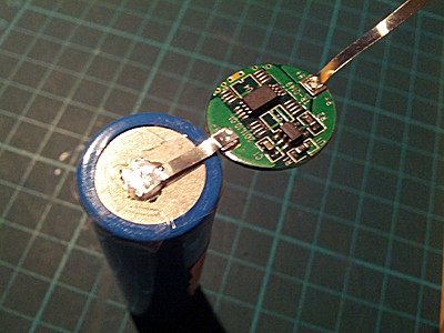
I don't care if an RSU is powered by a wall socket or is portable (although both would be nice), I just want to find out how to make a simple and reliable RSU that is affordable. There is nothing wrong with my 120-VAC $20 100W soldering iron, it works well. I am interested in attaching thick copper bus-ribbon to 18650 cells that can produce 30A each, and conventional soldering would require a long enough contact time that it would damege the cell electrolyte. Spot-welding thick copper is almost impossible without a machine that is $10K.

It looks like an RSU using 3V and 40A will work well, and this can be made fairly cheaply. The result should be simple, robust, and reliable.
 
A thought occurred to me, our favorite 18650's are unprotected by those tiny button-circuits sometimes found on one tip of a Vape cell. We have a BMS and the ebike controller to limit how many amps we pull. The Famous Samsung 25R is factory-rated for 20A, but in a dead short with nothing limiting the current, it can easily put out a two second burst of 40A (although it would definitely get hot).

What if our "amp adjustment" can be somewhat crude, perhaps in 5A steps? (or even smaller like 2A laptop cells, I'm just talking about the principle here).

Once the amps for a certain job were determined, we would only insert as many cells as needed to achieve those amps. That way, all the cells being used would be at the same level of charge (ie, if bringing a fresh cell into the circuit with the depleted cells, the high one would rapidly charge the low one)

The pic shows protected cells capable of 5A each, and it is configured for 15A of current at 4.0 volts. Would this work? Am I missing something?


Insulation%20between%20Battery%20Bottom%20and%20Protection%20Circuit%20%28Small%29.jpg
 
No control on the Amperage. Lets consider your first example the Samsung 25R. What is to keep it from putting out the 40 Amps rather than the 20 Amps you were planning on? On the other hand why not try a single Samsung 25R cell if it can dump the 40 Amps you are looking for? One would need some hefty FETs to switch that many Amps not to mention some very good connections to the 18650 cells.

But my real question is I somehow have it in my head that 'shorting' a cell is a very good way to destroy it. Is that just a myth I have some how picked up on?
 
You can have a very high-amp battery pack, but if you apply voltage across the leads with a very resistive load, only a small amount of current can get through. like a small headlight connected to a 70A battery, that can put out much more than the headlight is drawing (or, what the headlight is "allowing" to get through).

The tiny solder-blob I want to heat offers very little resistance (although it is enough resistance that it heats up) SAC305 solder is over 95% zinc, and the conductivity is roughly 27/100 compared to the copper probes and cables.

Maybe we can add several halogen bulbs on the cable (120VAC) to limit the current (series? parallel?). We can call them "Light Emitting Resistors". They come in small sizes too, so the steps can be fairly adjustable. 5, 10, 15, 20A...etc

Should the LER be on the battery positive side, or negative (to soften the pulse to the on/off FETs). or...one on each side?

PortableRS1.png
 
spinningmagnets said:
Maybe we can add several halogen bulbs on the cable (120VAC) to limit the current (series? parallel?). We can call them "Light Emitting Resistors".
:lol: :lol:
Many years ago my best friend had a 1959 Rambler (we called the rattler) with a 12 volt electrical system. In those days an audio system (AM Radio) was an optional piece of equipment that the original owner had not selected. We extracted a AM radio from a junked Rambler but it was 6 volts. So we went to see our friend who was more knowledgeable on such things. He had us wire a High Beam headlight in series with the radio. Worked like a charm except every time you turned on the radio there was a very bright light inside the car.

P.S. His girl friend was NOT pleased when she decided some mood music was needed one night.
 
Just realized I confused two different threads. This portable unit operates on DC and should use a lower voltage 4V. Yes, a 6V bulb would be an easy experiment. Maybe even 12V bulbs would work too?
 
Need to measure the actual resistance of the leads, probes, copper strip, solder and battery in a proposed configuration. Then ohms law can be applied to determine if there is a problem or if additional measures are needed. I think the the first step may be to build the leads and probes.

Here is another couple of questions for you:
1) What are the dimensions of your coppers strips (thickness and width)
2) For the cell anode: are you going to be able to get one contact on the anode and one on the strip or will you be forced to place both contacts on top of the strip?
Battery Anode Example 01.jpg
In the first case current flows from probe 2, through the copper strip, solder and steel anode to tip 1.
In the second case current flows from probe 4, through the copper strip to tip 3. Heating takes place by transfer from the steel probes to the copper strip.
(Note: round ends on the probes are probably not the optimum choice)
 
I think a good starting size would to try would be copper, 7mm wide and 0.20 thick. It would conduct four times better than 0.20mm nickel, and six times better than 0.15mm nickel. The 7mm width would fit into the 8mm slots on the common cell holders.

It would be awesome if RS would work well for 0.25mm-40mm copper (and I think it will). The plumber videos I saw clearly show that extra thick copper pipes can be well-bonded using RS. All that will change is the volt and amp settings. The only concern is if the required settings allow too much heat to penetrate into the battery electrolyte.

I've considered having a slot in the center of the strip. One probe on the center, and a forked probe pressing down on the two halves of the strip? Maybe a hole in the center of the strip, just over the cathode? Easy to experiment a variety of options, once I can get started. Maybe two narrow strips side-by-side, but thicker...to make the same cross-section of copper?
 
Yep, at 7mm it is going to be hard to reach the steel anode.
I've considered having a slot in the center of the strip. One probe on the center, and a forked probe pressing down on the two halves of the strip?
H'mmmm that might require some dedicated, well constructed probes ....Battery Anode Example 02.jpg
First example is three 2.5mm ground and insulated with Kapton tape. That is a 2mm hole in the center of the copper strip.
Second example is a SST tube (3mm ID x 5mm OD) and a 2mm brass center probe. Same 2mm hole in center of 7mm wide copper strip.
The second might actually be easier to build and it applies the probe resistance heat and pressure evenly around the top of the copper.
It should be obvious but the brass center probe must be insulated from the SST sleeve.

Reference:
304 Stainless Steel Capillary Tube
http://www.ebay.com/itm/371187195837
(never draw anything made of unobtanium)

PS
Ever consider the idea of soldering M3 or M4 hex nuts to each end. Then the buss bars could be mechanically attached (and more importantly removed).
 
Thanks for the drawings, that's a big help. I knew what I was thinking in my head, but sometimes my words don't convey an accurate picture. I am certain we can figure something out that will work very well.

Although I like the idea of using 12 X 3mm neo button magnets to hold a copper strip against the broad and flat negative of the cells, I believe this will also work well for that end. Of course, that end is much easier to experiment with, so I am concentrating on the hard part, the small positive nipple.

I also like the idea of resistance-soldering a fuse-wire to the positive nipple. That being said, A lot of builders want a more solid connection from a flat ribbon to the positive, and I believe we can figure out a really good way to do that.
 
It is possible to over think a problem. Is it possible the simplest solution could work just as well. The first example below is two 4mm square SST bars separated by a piece of 1mm thick phenolic sheet (aka bakelite, PCB board, ect.) and ground down to 2mm thick at the business end. All the heat would be generated in the tip but would be concentrated in a small area of the top of the copper strip. Short duration, high temperature contact heat transfer to the copper, solder, cell in that order.

Second example is I wanted to see what a M3 copper nut looked like on top of an 18650 cell. The 3mm size may sound small but keep in mind that it is almost the equivalent of a 8 AWG copper wire.Battery Anode Example 03(799).jpg
 
Back
Top