Kodin
1 kW
Welp, been lurking long enough, here's the start of my build thread.
BACK TO THE DRAWING BOARD (April 2018)
MAY 2019:
And this is where I leave you once again hanging... The project has once again stalled due to funds, as I need a decent battery for this rig. Once I budget for that and purchase the packs, I'll pull the hubmotor off the frame, take photos, wire up phase/hall wires, close it up, add Statorade, (Is it trademarked? Do I need to put the TM sign after it?), mount the controller, wire up the controls, and hopefully not kill myself the first time I get on this thing and twist the throttle. I hope to get back to this project this summer.
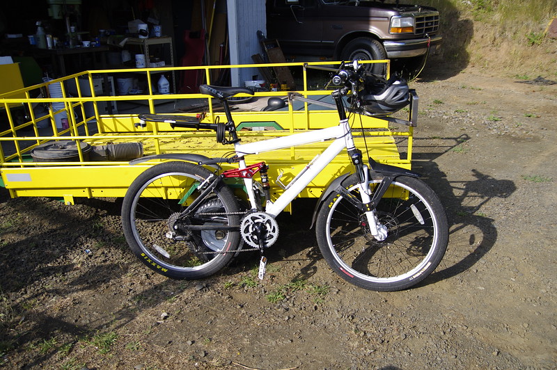
Genesis V2100 I got for free due to a funky ebay scam that caused the seller to get their account shut down. ~$700 in parts later, and the frame and handlebar are the only original parts of the bike.  Suspension also now has sealed bearings on all moving parts except the main swing-arm pivot. (That will come next.)
This is before I've even thought of adding any electronics to it other than a bike light.
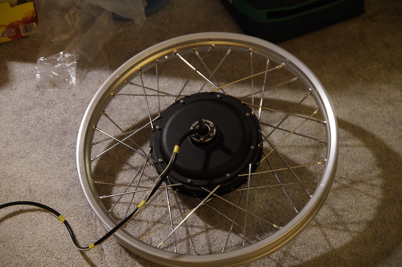
Bought a Leafbike 1500W with 3mm² phase wires, thermistor, and 5t wind. I then ordered separately a set of side-covers and shaft to run a freehub rather than freewheel. Motor will be oil-filled if I can figure out a good way to do it, but for now I'm going to run it stock until I have time to modify the motor.
Spokes are 3.5mm motorcycle, in a 2-cross pattern, laced into a DID 21x1.6" motorcycle rim. I had to enlarge the flange holes ever-so-slightly to get the spokes to fit through the flanges. (I did this to an interference fit; literally have to screw them through the holes at the threaded section I made them so tight).
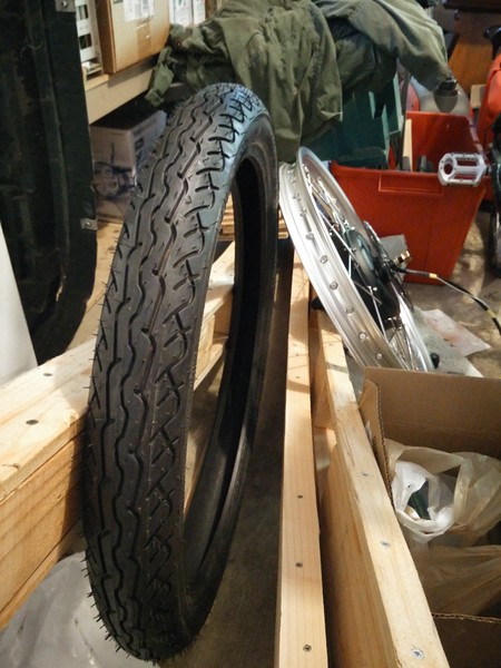
I'll be putting a Pirrelli MT66 80x90-21 on the whole thing.
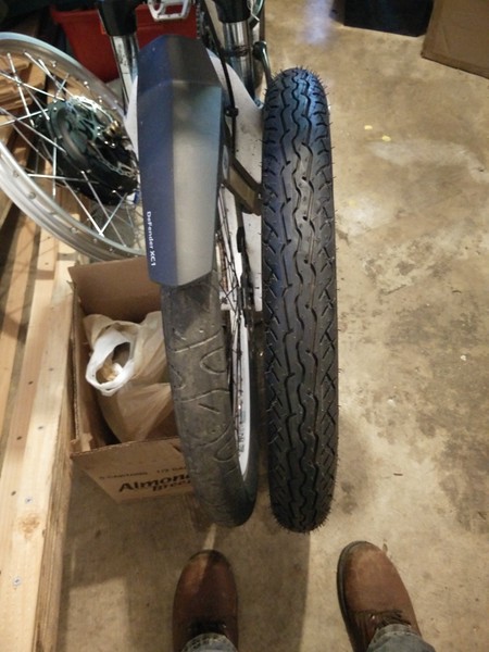
The whole thing ends up being the exact same outer diameter as my 26" MTB rims with 2.5" Hookworms, though maybe 1/4" wider.
Controller is a Sabvoton SSC048150. Yes, it's total overkill to use a controller capable of 150A. Regardless, due to cost reasons I figured 20Ah/12S Multistars would be "enough" to get started, and I didn't want to target 72V straight off the bat. Regarding 150A controller choice, I figure when I DO move to 72V, I can re-use the 48V controller for something else.
[EDIT: Turns out this controller uses 4110 FET's, so likely can be reprogrammed for use up to 96V. Honestly I don't think I'll need to buy another controller until my next build at this point.]
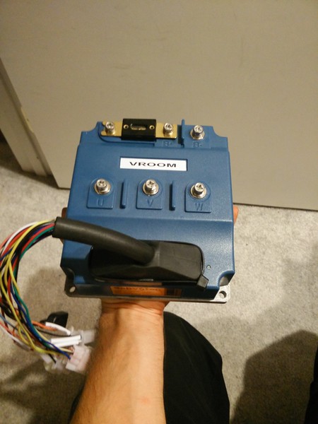
Just a wee little controller, eh?
This is before I've even thought of adding any electronics to it other than a bike light.

Bought a Leafbike 1500W with 3mm² phase wires, thermistor, and 5t wind. I then ordered separately a set of side-covers and shaft to run a freehub rather than freewheel. Motor will be oil-filled if I can figure out a good way to do it, but for now I'm going to run it stock until I have time to modify the motor.
Spokes are 3.5mm motorcycle, in a 2-cross pattern, laced into a DID 21x1.6" motorcycle rim. I had to enlarge the flange holes ever-so-slightly to get the spokes to fit through the flanges. (I did this to an interference fit; literally have to screw them through the holes at the threaded section I made them so tight).

I'll be putting a Pirrelli MT66 80x90-21 on the whole thing.

The whole thing ends up being the exact same outer diameter as my 26" MTB rims with 2.5" Hookworms, though maybe 1/4" wider.

Controller is a Sabvoton SSC048150. Yes, it's total overkill to use a controller capable of 150A. Regardless, due to cost reasons I figured 20Ah/12S Multistars would be "enough" to get started, and I didn't want to target 72V straight off the bat. Regarding 150A controller choice, I figure when I DO move to 72V, I can re-use the 48V controller for something else.
[EDIT: Turns out this controller uses 4110 FET's, so likely can be reprogrammed for use up to 96V. Honestly I don't think I'll need to buy another controller until my next build at this point.]

Just a wee little controller, eh?
So I, like most of you who run reasonably torquey motors should be, was concerned with motor shaft spin-out. As such, I originally thought I'd order a Farfle swing-arm for my frame. Sadly, Farfle is out of that business. Fortunately, Barent Hoffman has taken up the design and had parts cut out to continue providing these to the community. I wanted to build my own, so I ordered the plasma-cut parts from Barent and started building. All laser-cut parts are mild steel, the tubing will be chromoly.
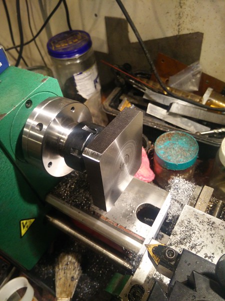
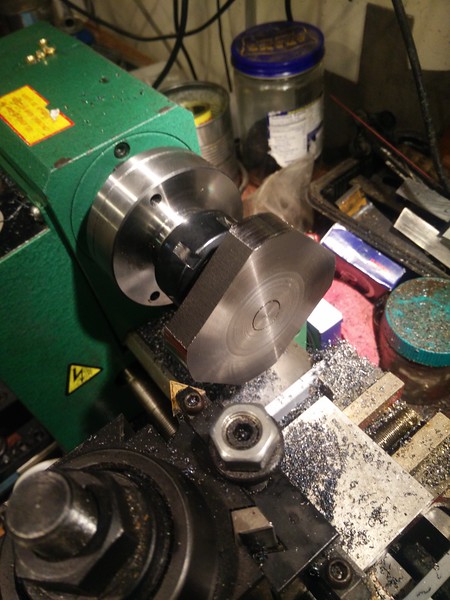
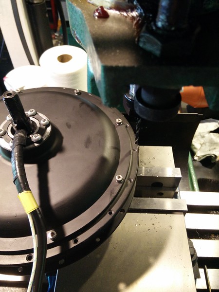
Dropouts were modified to admit a clamping bolt, as I want to be extra paranoid and give room for potentially larger or more powerful motors in my future. As such, the first thing I did was clamp them in my milling vice, cut them for mounting tubing, and weld in tubes to the ends for clamping bolts:
Cut:
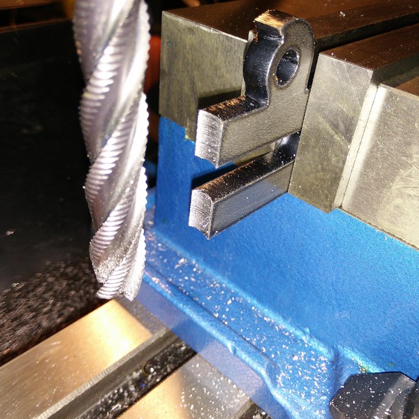
Test-fit:
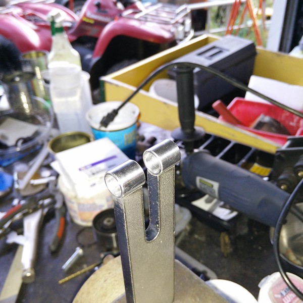
Weld:
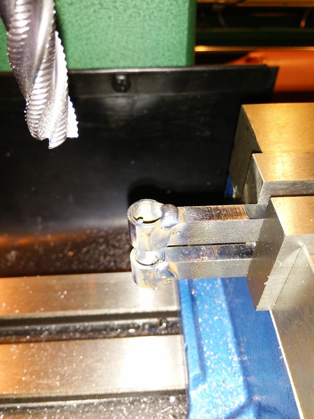
Mill bolt contact surfaces flat:
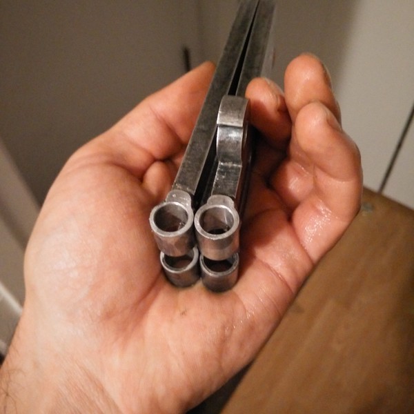
Final product:
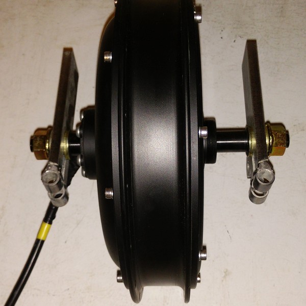
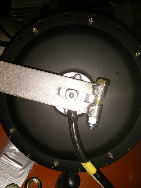
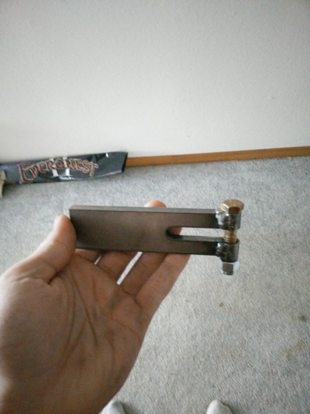
More on this later, as I build the rest of the swing-arm...
Dropouts were modified to admit a clamping bolt, as I want to be extra paranoid and give room for potentially larger or more powerful motors in my future. As such, the first thing I did was clamp them in my milling vice, cut them for mounting tubing, and weld in tubes to the ends for clamping bolts:
Cut:

Test-fit:

Weld:

Mill bolt contact surfaces flat:

Final product:


More on this later, as I build the rest of the swing-arm...
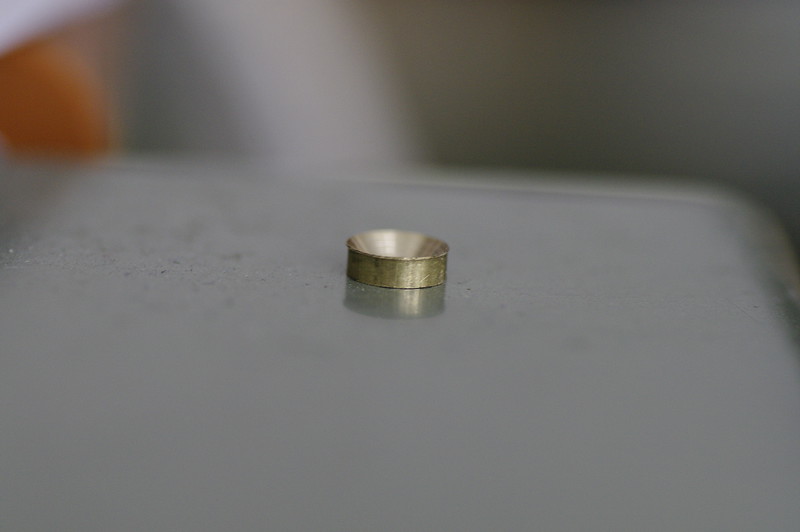
I started making some brass washers for my spokes; the flange thickness for the 3.5mm spokes I got was ~0.080" wider than the actual flanges on my motor, and I wanted them to locate as close to the elbow as I could manage without causing problems. Made from 1/4" solid brass bar, drilled, parted, and countersunk at an appropriate angle to match the flare on the end of the spokes. Flare angles don't quite match up perfectly, which is good; gives about 1-2 degrees of play, so the spokes can angle as required off the flange. Made 5 last night before/after lifting my rebuilt transmission back into my truck, and I'll probably finish off the remaining 31 today. I'll update this post with more "making of" pictures as I go.
Here's a couple I took with my cell phone of the prototype and following 4 I made while trying to figure out a good process for making lots of them:
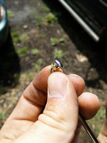
First prototype made!
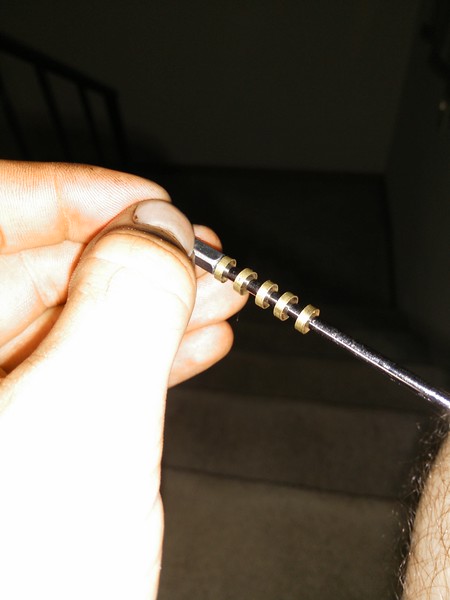
Here's all 5 I made last night on one of my spokes:
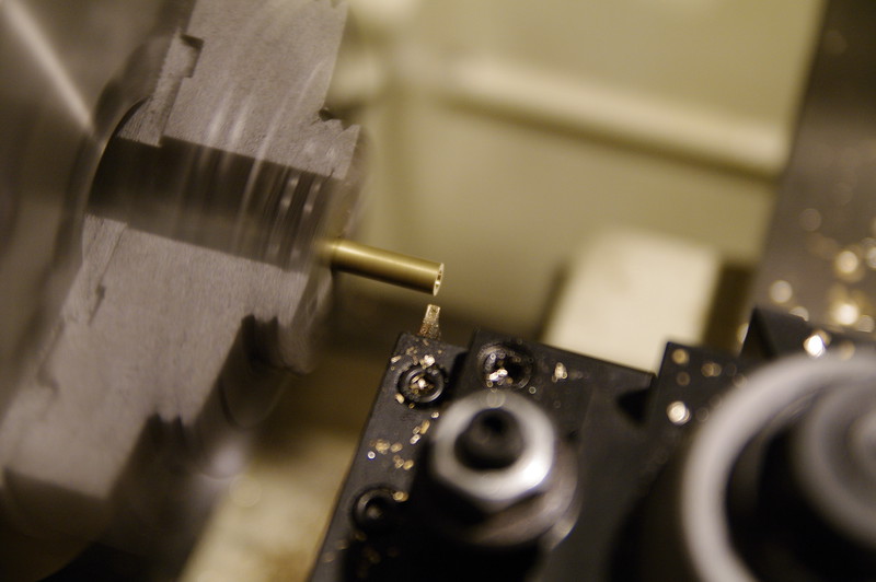
My parting inserts were ~0.085", (supposedly 2mm-ish), so I'd face cut a new bar with the parting tool, zero my DRO, center-drill to get a good center, drill the rod through with a long parabolic 3.5mm bit an inch or two,
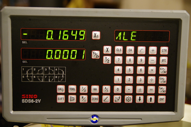
Then advance 0.165",
Part off,
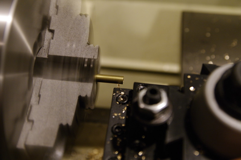
Zero, repeat.
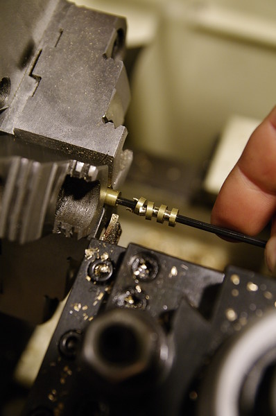
Now I move from the big lathe to the small one for finishing; not because I need to, but because it's faster and the big lathe doesn't have a collet chuck, not to mention the time it would take to swap chucks would make this workflow impractical for 36 identical parts.
They look like this after parting; Since it's small brass and I'm doing 4-5 at a time before advancing the rod in the chuck, the whole rod flexes when I part and leaves these sharp bits. Easy enough to fix in the next step.
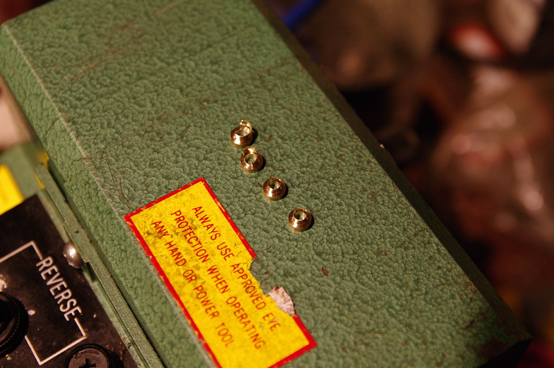
The 3.5mm hole wasn't wide enough to clear the threaded section of my spokes, so I enlarged that with a second drill. Normally you can't work on stuff this stubby, but I have an el-cheapo 7x8 harbor freight mini lathe I've upgraded to a 7x14 with proper tapered roller bearings and all kinds of other stuff, (upgrades cost more than the lathe did originally,) and I'm running an ER32 collet chuck on it. Collet chucks are amazing for this sort of thing as they will grip round stock of literally almost any length with equivalent to about 8-12 jaws. That means I can put a part that's only 0.080" long into it and it'll grip hard enough to stay without distorting it on the outside.
So I push the spacers into the collet a bit, with the parted side facing out, as they usually have a bit of a lip still stuck on the end.
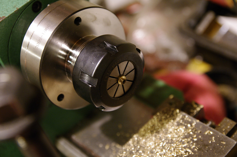
I push them into the collet flush using a washer that's about the right size.
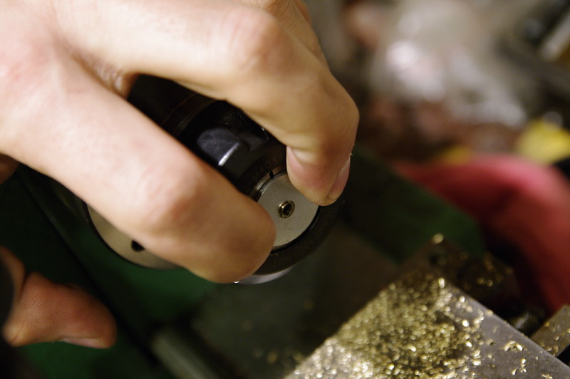
This aligns them axially and makes sure they are mounted in approximately the right depth every time.
Then I tighten the chuck and drill them out to the final diameter on the small lathe.
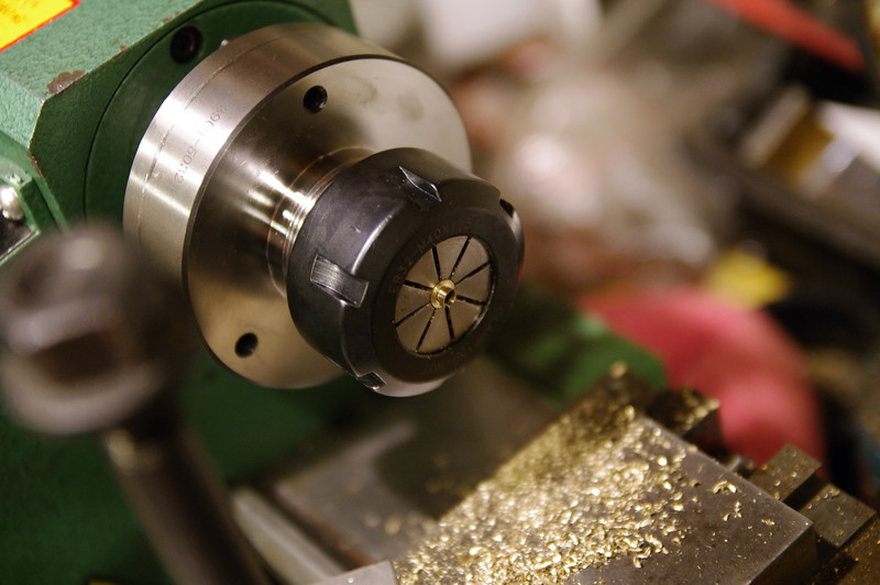
Once drilled through, I swap tailstock chucks to one with a small 6-tooth countersink bit, and plunge by eye (as I don't have any indicators or DRO's to measure depth on the small lathe,) until the taper almost becomes a knife edge on the periphery.
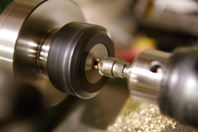
Loosten chuck, take a small rod and pop the part out from the rear of the spindle bore, on to the next one.
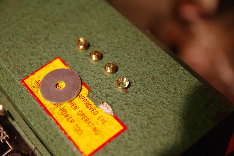
I'll probably forego the first drill step for the rest as I'm thinking at this diameter it's unnecessary to add an extra step; should speed me up quite a bit as well since I'm building a lot of these little buggers.
Now up to 12!
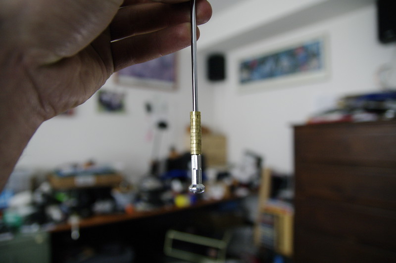
Unfortunately, I've also produced two "duds" which were countersunk too deep and started to flare out on the periphery.
Skipping the first drill step is definitely faster. I was able to do 10 in ~17 minutes, from start to finish.
One quick tip on working with brass: If you drill it, knock the sharp leading edge on the tip off your drill bits. Brass likes to grab really hard if you have a positive rake drill bit; (literally like 99% of all metalworking drill bits use a positive-rake leading edge). When that happens, the bit basically acts like a screw, plunging in without removing material. At best you get lots of chatter, at worst your drill bit breaks inside the part. Buy a cheap set of drill bits, take a stone and swipe it once or twice across the leading edge of each one, and throw them in a bucket labeled "for use on brass". You essentially have made the leading edge into a zero-rake tool geometry, without making the bit completely dull. Makes a HUGE difference and it'll keep you from breaking your bits or causing weird things to happen while drilling.
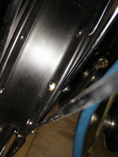
Update - 2015/09/07 - Did another 6 in 10 minutes while waiting for some pizza to bake. Also de-laced all of the spokes so I can start reassembly. Halfway there!
Also, yes, they do fit.
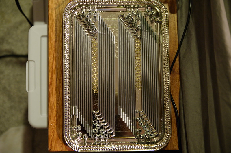
Update - 2015/09/08 - Finished all the spacers. Gratuitous OCD picture because I can:
I'm using a DID 21x1.6" aluminum motorcycle rim. Super beefy. Here it is test-laced in a 2-cross pattern when I first got all the parts. This was before I made the brass spacers.

Spokes are 3.5mm in diameter, so I had to drill out the flange holes slightly. Holes are not drilled perfectly concentric to the shaft bearings; they vary ~1mm or so in and out. I discovered this while drilling the holes larger.
The tire I bought is a Pirelli MT66 front tire, in the 80/90-21 size.

This means it's 80mm tall with a 90% height-to-width ratio. Means this tire is slightly taller than it is wide, but I was worried about chain lines in granny gear, and this looked like a good size to start with.
Here's a comparison to my 26x2.5" Hookworms.

Compound feels just as grippy if not more so than the Hookworms, and this tire is STIFF. As in when they shipped it, they wrapped packing tape around it and shipped it as-is. It holds it's shape really well compared to the Hookworms. It's a tubed-type tire, so it's rated to be ridden with a tube in it; I figured that was the best option for this build. I can't wait to see what it feels like on the road.
Update: As other projects have taken my time and my lathe dogs hadn't arrived yet to do center turning, I re-laced the rotor to my rim with the brass spacers.
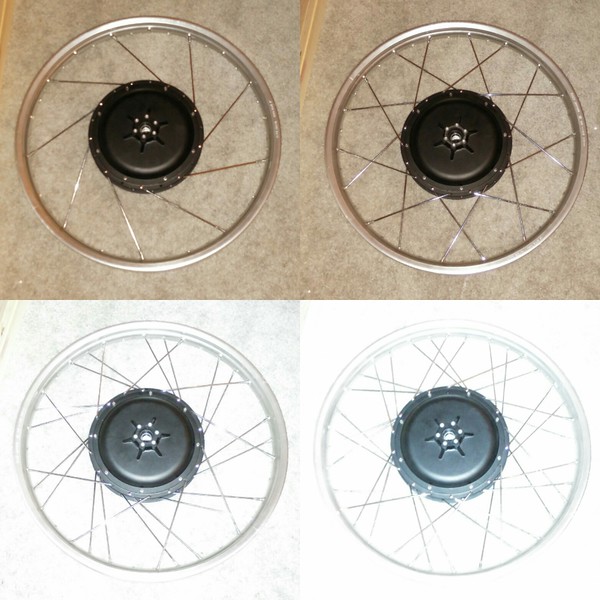
Not sure if spokes vary slightly in elbow length or if my brass spacers thickness vary at the countersink, (did them all "by eye" for depth), but a few of the spokes feel somewhat tight. Might pull off the tight ones and cut them down ~0.001mm or so to get them perfect, but for now I'm pretty happy with my batch part build.
Here's a couple I took with my cell phone of the prototype and following 4 I made while trying to figure out a good process for making lots of them:

First prototype made!
Here's all 5 I made last night on one of my spokes:

My parting inserts were ~0.085", (supposedly 2mm-ish), so I'd face cut a new bar with the parting tool, zero my DRO, center-drill to get a good center, drill the rod through with a long parabolic 3.5mm bit an inch or two,

Then advance 0.165",

Part off,

Zero, repeat.

Now I move from the big lathe to the small one for finishing; not because I need to, but because it's faster and the big lathe doesn't have a collet chuck, not to mention the time it would take to swap chucks would make this workflow impractical for 36 identical parts.
They look like this after parting; Since it's small brass and I'm doing 4-5 at a time before advancing the rod in the chuck, the whole rod flexes when I part and leaves these sharp bits. Easy enough to fix in the next step.

The 3.5mm hole wasn't wide enough to clear the threaded section of my spokes, so I enlarged that with a second drill. Normally you can't work on stuff this stubby, but I have an el-cheapo 7x8 harbor freight mini lathe I've upgraded to a 7x14 with proper tapered roller bearings and all kinds of other stuff, (upgrades cost more than the lathe did originally,) and I'm running an ER32 collet chuck on it. Collet chucks are amazing for this sort of thing as they will grip round stock of literally almost any length with equivalent to about 8-12 jaws. That means I can put a part that's only 0.080" long into it and it'll grip hard enough to stay without distorting it on the outside.
So I push the spacers into the collet a bit, with the parted side facing out, as they usually have a bit of a lip still stuck on the end.

I push them into the collet flush using a washer that's about the right size.

This aligns them axially and makes sure they are mounted in approximately the right depth every time.
Then I tighten the chuck and drill them out to the final diameter on the small lathe.

Once drilled through, I swap tailstock chucks to one with a small 6-tooth countersink bit, and plunge by eye (as I don't have any indicators or DRO's to measure depth on the small lathe,) until the taper almost becomes a knife edge on the periphery.

Loosten chuck, take a small rod and pop the part out from the rear of the spindle bore, on to the next one.

I'll probably forego the first drill step for the rest as I'm thinking at this diameter it's unnecessary to add an extra step; should speed me up quite a bit as well since I'm building a lot of these little buggers.
Now up to 12!

Unfortunately, I've also produced two "duds" which were countersunk too deep and started to flare out on the periphery.

Skipping the first drill step is definitely faster. I was able to do 10 in ~17 minutes, from start to finish.
One quick tip on working with brass: If you drill it, knock the sharp leading edge on the tip off your drill bits. Brass likes to grab really hard if you have a positive rake drill bit; (literally like 99% of all metalworking drill bits use a positive-rake leading edge). When that happens, the bit basically acts like a screw, plunging in without removing material. At best you get lots of chatter, at worst your drill bit breaks inside the part. Buy a cheap set of drill bits, take a stone and swipe it once or twice across the leading edge of each one, and throw them in a bucket labeled "for use on brass". You essentially have made the leading edge into a zero-rake tool geometry, without making the bit completely dull. Makes a HUGE difference and it'll keep you from breaking your bits or causing weird things to happen while drilling.
Update - 2015/09/07 - Did another 6 in 10 minutes while waiting for some pizza to bake. Also de-laced all of the spokes so I can start reassembly. Halfway there!
Also, yes, they do fit.

Update - 2015/09/08 - Finished all the spacers. Gratuitous OCD picture because I can:

I'm using a DID 21x1.6" aluminum motorcycle rim. Super beefy. Here it is test-laced in a 2-cross pattern when I first got all the parts. This was before I made the brass spacers.

Spokes are 3.5mm in diameter, so I had to drill out the flange holes slightly. Holes are not drilled perfectly concentric to the shaft bearings; they vary ~1mm or so in and out. I discovered this while drilling the holes larger.

The tire I bought is a Pirelli MT66 front tire, in the 80/90-21 size.

This means it's 80mm tall with a 90% height-to-width ratio. Means this tire is slightly taller than it is wide, but I was worried about chain lines in granny gear, and this looked like a good size to start with.
Here's a comparison to my 26x2.5" Hookworms.

Compound feels just as grippy if not more so than the Hookworms, and this tire is STIFF. As in when they shipped it, they wrapped packing tape around it and shipped it as-is. It holds it's shape really well compared to the Hookworms. It's a tubed-type tire, so it's rated to be ridden with a tube in it; I figured that was the best option for this build. I can't wait to see what it feels like on the road.
Update: As other projects have taken my time and my lathe dogs hadn't arrived yet to do center turning, I re-laced the rotor to my rim with the brass spacers.

Not sure if spokes vary slightly in elbow length or if my brass spacers thickness vary at the countersink, (did them all "by eye" for depth), but a few of the spokes feel somewhat tight. Might pull off the tight ones and cut them down ~0.001mm or so to get them perfect, but for now I'm pretty happy with my batch part build.
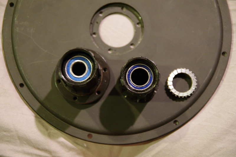
So I've been having some concerns about shaft thickness on the cassette side, since the cassette provided can accommodate a maximum of 12mm diameter shaft. This bugs me.  I have a DT-Swiss ratchet hub that uses a 15mm shaft, and it got me wondering; can I bore out my Leafbike hub and use a larger inner-diameter bearing to let me run a 15mm shaft all the way through? My only other option is to build a blind spline broaching tool and build a mating side for my DT-Swiss hub, which I'm less than inclined to do at the moment... It'd require creating the spline for the ratchet to slide in as well as a mounting flange that matches the Leafbike design. Though I have a couple rotary tables, broaching that kind of spline is going to drive me nuts. I'll try to take the Leafbike hub apart tomorrow and see what I have to work with. If I'm making a new shaft, increasing the hub's inner bore would be best to maximize the "meat" I have available on the right side of the shaft.
Picture for comparison:
UPDATE: Problem solved for the DT Swiss option, if I end up going that route; the hub end spline apparently is a thread-in deal; Broaching would be a PITA, but threading is relatively easy.

UPDATE 2: Made a tool to disassemble the hub, and it's a style you really do NOT want to try boring out much... I might be able to get away with 1-2mm, (About all I want honestly,) but I can't guarantee it won't affect the strength of the hub going forward. I'll take some pictures tomorrow and consult a fellow machinist in the morning, watch for another update Monday.
UPDATE 3:
Cassette A: is SUPER FREAKIN' HARD STEEL!!! Like I don't even KNOW what this crap is made of, but carbide BARELY cuts it! I enlarged the bore from 3.4mm to 3.5mm and that's about as far as I've been able to remove. Tried an adjustable reamer with steel blades and the cutting surfaces rounded off.
Pics of cassette design taken apart:
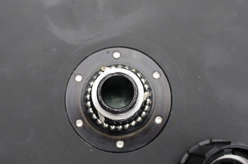
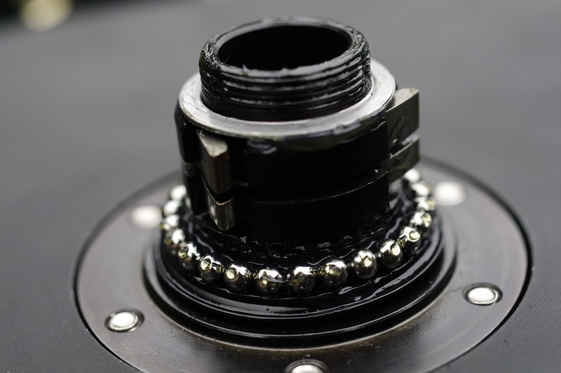
Really starting to think Plan B is the better option:
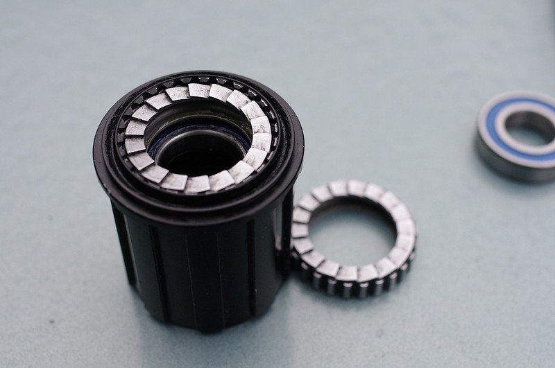
UPDATE 4:
So I tried boring again, and it turns out that the cassette just had a massively hard surface layer. Unfortunately, my steel-shanked carbide boring bar swayed back into place once it cut through this, and over-bored by 0.6mm more than I wanted. Sure is gonna be iffy, but I think I can probably live with it for the moment. My 6-foot bar of 4340 arrived as well, so I may start roughing out the shaft tonight. As always, keeping y'all posted!
UPDATE 5:
Turns out I'm a complete derp, and the bearing I wanted to put in was 15mm; I'd targetted 14mm for shaft diameter. Just threw the hub back in the lathe and got it bored to 15.15mm exactly. Should avoid contact with the shaft, and it'll let me run 15mm all the way out to the threads. The original shaft only goes to 13mm in comparison. This should actually be stronger than a non-cassette wheel when I'm done!
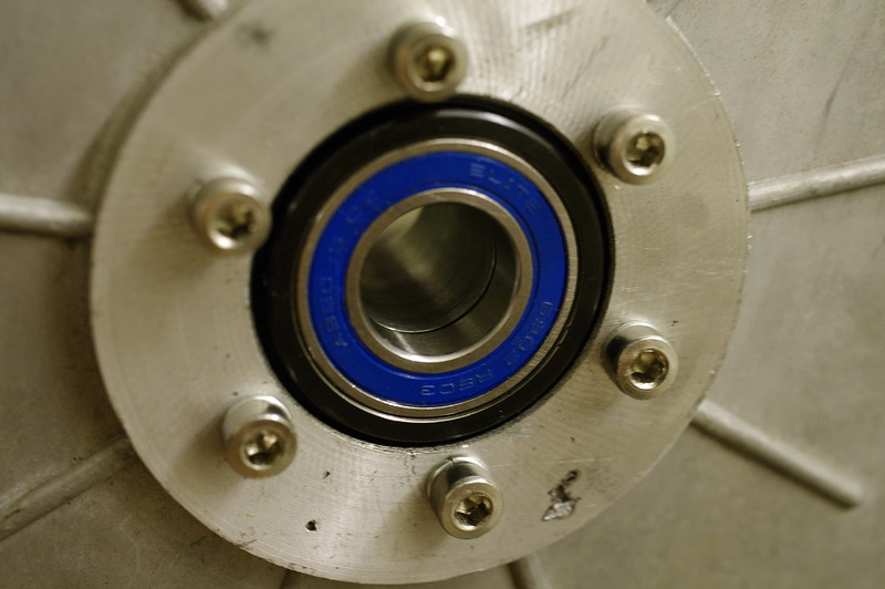
Bearing inner is 15mm exactly, bore is 0.15mm larger.
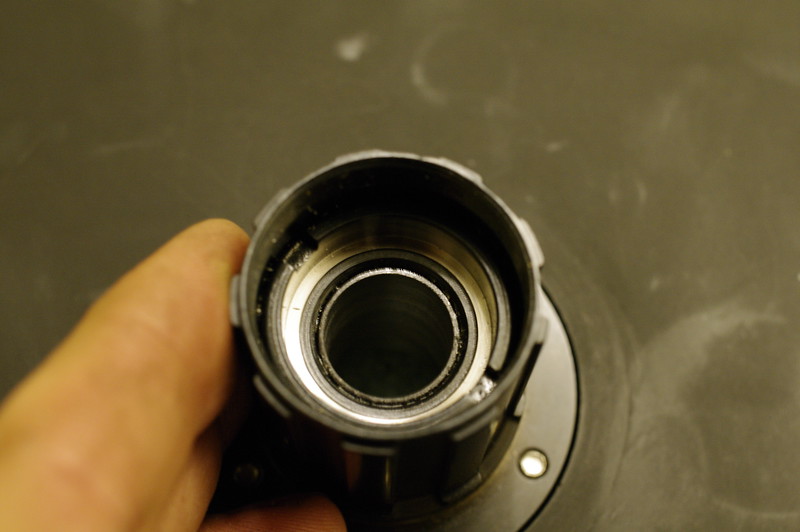
Not much meat left on this guy, but really it shouldn't exert a lot of load, and I'm going to back it up with a tubed-nut to retain the bearing(s) anyway.
Derp #2: I lost one of the balls from the cassette. It shot off and has attained freedom where all small highly mobile parts such as springs and ball bearings hide in my shop. Now I'll have to measure the bearing diameter and order a pack of them; might as well anyway so I have spares. What's a good grease to use in cassettes? I'll probably want to drop the whole thing in my ultrasonic and re-grease just in case any of the cutting chips got inside the bearing surfaces anyway.
Update - 2015/09/15 - Popped the motor open today, looks very clean; in fact, maybe cleaner than Neptronix's motor.
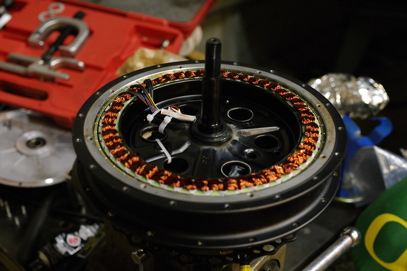
...Aside from this random piece of copper wire....
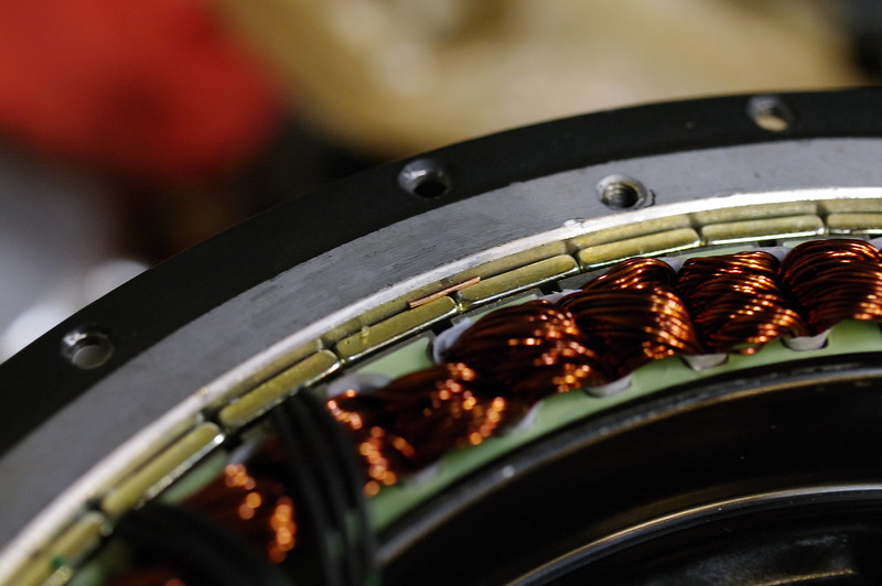
One of the halls doesn't look perfectly aligned...
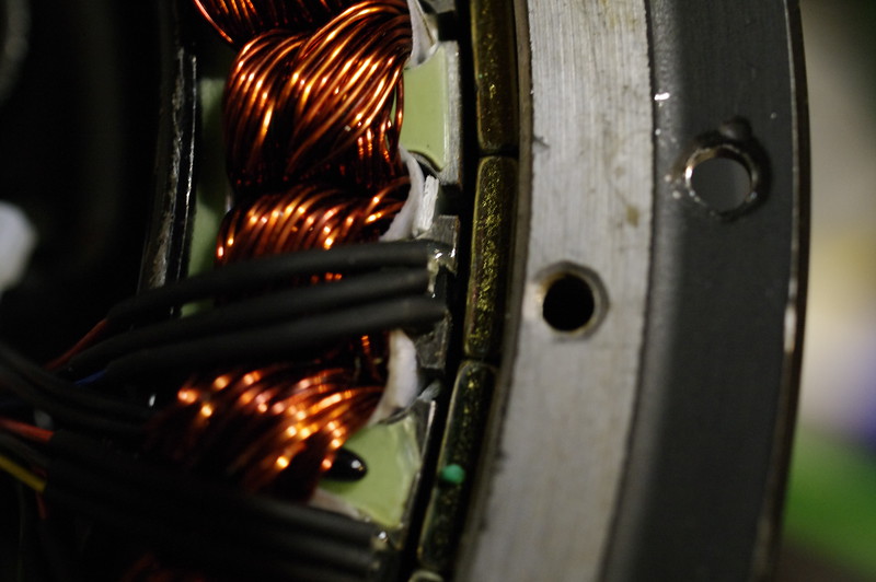
The rest are OK, though not as far out as they could be. There's slots for halls on the other side of the stator as well; I may order a few and swap out all of them with new ones aligned correctly; we shall see...
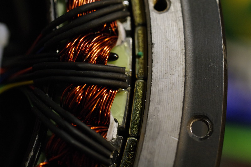
Also note the temp sensor poking out from under the windings... Hey there little guy!
Pulled the freewheel cover and magnets with this arrangement. Single-speed freewheel is a beast, I doubt it was damaged in the slightest from the (mis)treatment.
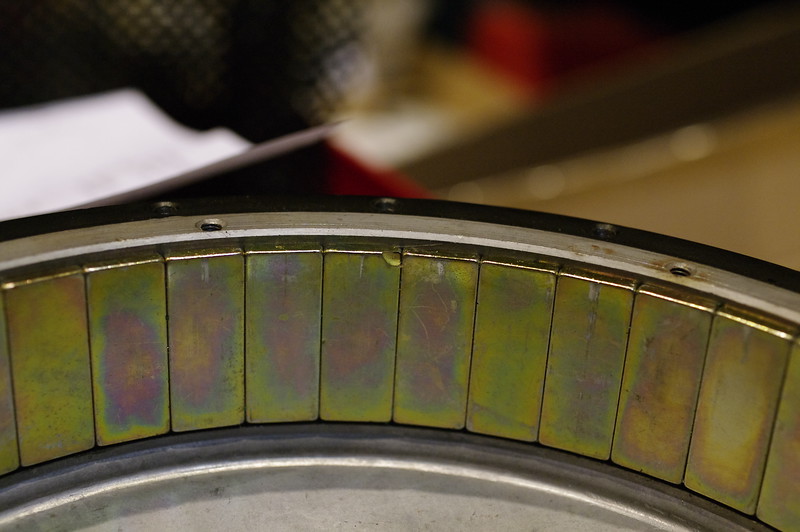
There was ZERO gap between any of my magnets, meaning they cut the right diameter for my motor; Neptronix's had had an issue where there was a gap, this just means that his can was fractionally larger in diameter than was optimal.
Only issue I see is one of my magnets is missing a tiny corner:
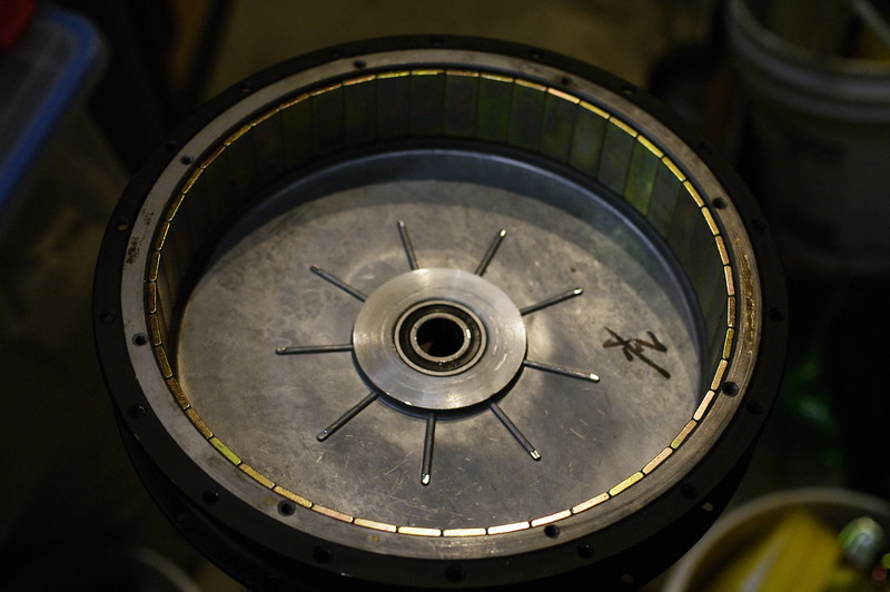
Oddly, the vanes were machined down on the ends on the freewheel cover. I have no idea why; I don't think there's anything even remotely near that they can hit...
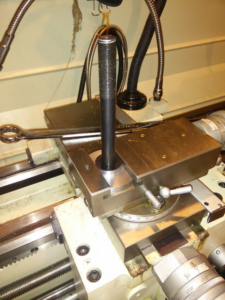
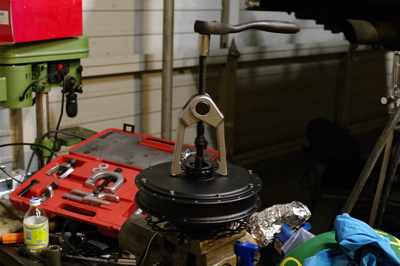
I turned down a water pipe coupler and cut a slot in it to avoid the cable bundle; should let me (eventually) press the bearing out of the brake-side cover without mangling the wire bundles.
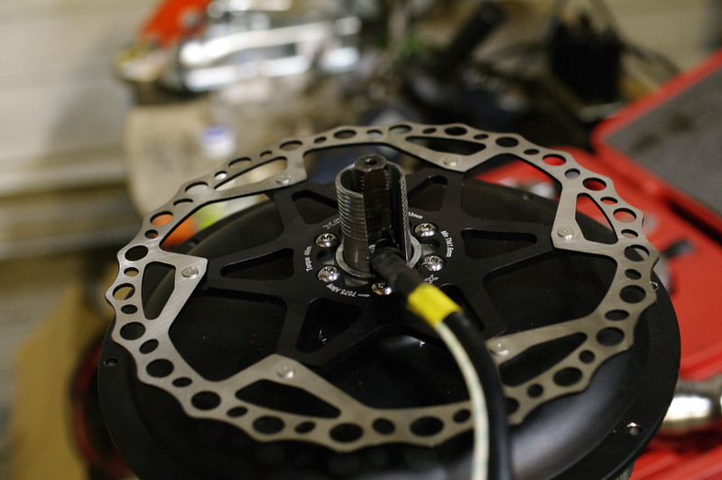
Makes enough contact with the inner race of the bearing that it should allow me to slide-hammer or press it out; my next challenge is figuring out how to support the darn side cover with enough surface area that it A: doesn't distort, and B: pops the bearing. Seems like either they pressed in the bearings with a crap-ton of force, or they used some sort of glue or locktite.
October 2015: Got 'er removed; turns out that the shaft necks down enough to allow the bearing to pop and be removed without damaging the wire bundle. It's tight, but the cable doesn't even kink. Hardest part of the whole process was de-pinning the hall connector to remove the side cover, then re-pinning in the same configuration afterward.
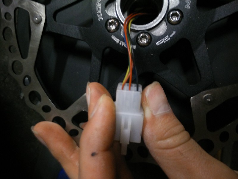
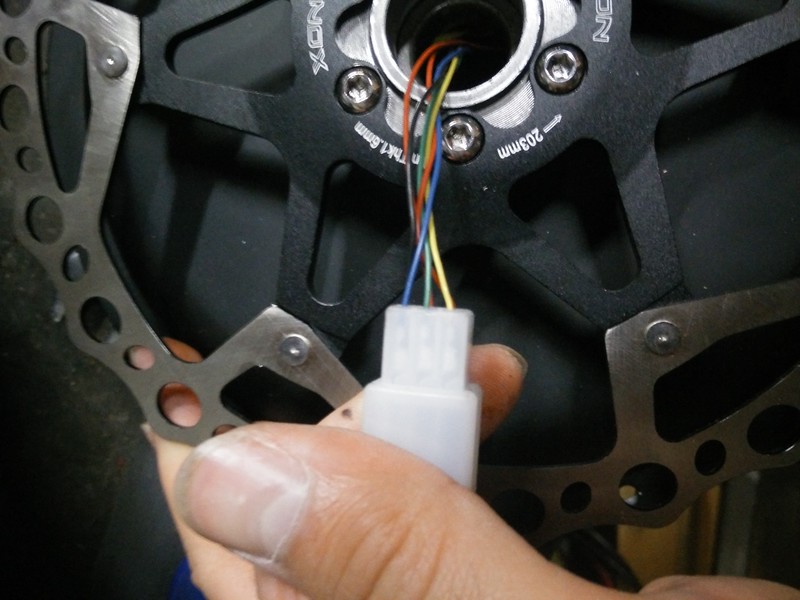
(I've seen TONS of examples that show the wire color scheme may or may not match between motors; Especially with the temp sensor wire color. As such, use mine as reference, but don't take it for granted that it's correct for your motor).
Here it is separated:
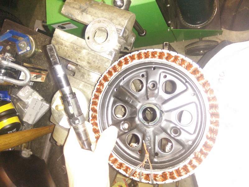
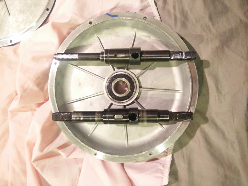
Here's the comparison of the two styles of shaft:
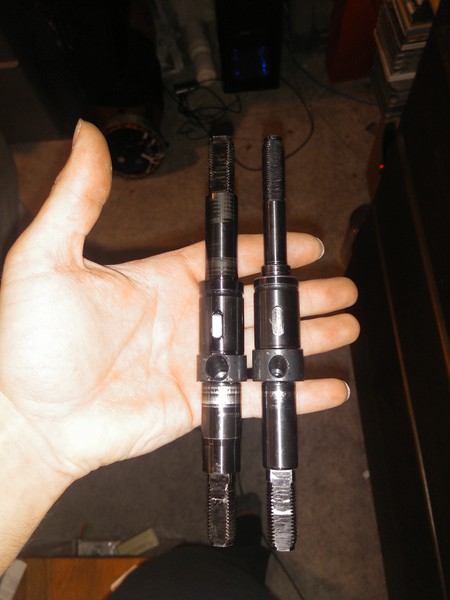
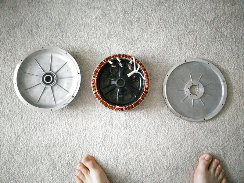
And here's the three parts I'll be installing:
Brake rotor side has two different designs; one has a round profile, one has gussets:
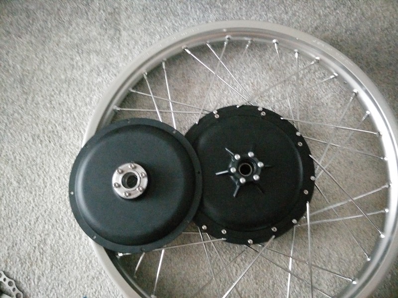
I like the fully round version as my brake rotor mounts perfectly on it:
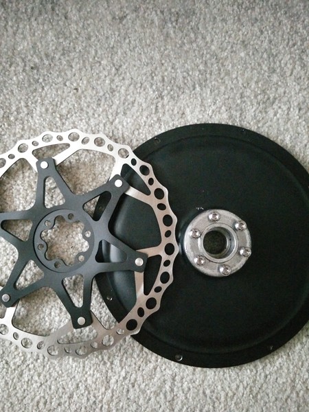
The gusset version has protrusions that exceed the diameter of the cut-out in the carrier on my rotor. I could always simply cut them down at the contact area if I really needed to, but it's still a consideration to make when speccing out parts. I suspect Leafbike used the round-mount design for my build because it supported a larger diameter shaft for the 3mm² phase wires with larger diameter bearings; I'll confirm this later.
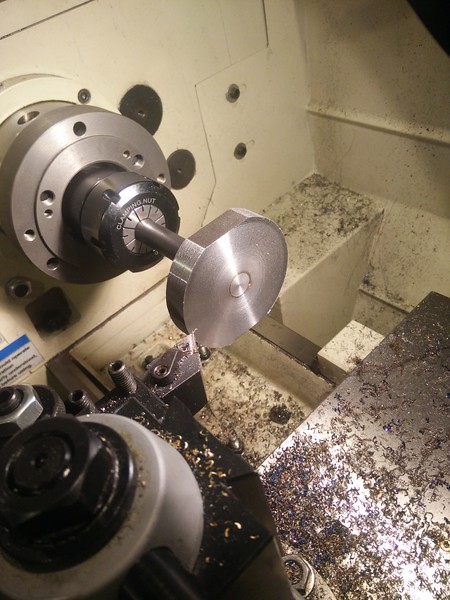
Lastly, here's my first (terrible) cut of 4340:
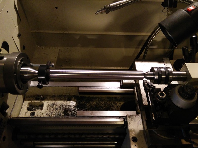
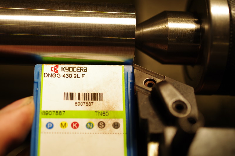
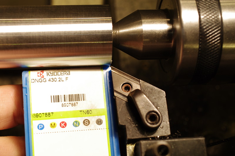
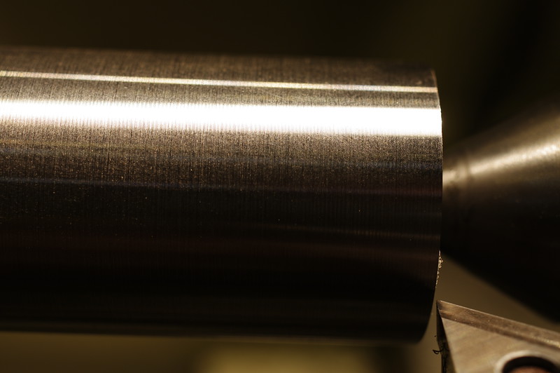
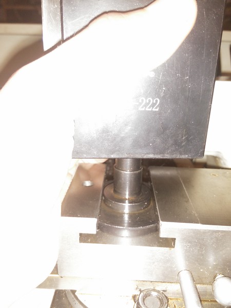
Lathe cuts just fine, but I'm going to wait for a new wedge-type BXA tool post to arrive before I make any further cuts. I suspect my piston type is allowing a bit of "give" in my tooling. Either way, this stuff work-hardens a lot, so I'm not expecting totally beautiful results for a while. I'll likely draw-file to final diameter. Further, this is the first center-to-center cutting I've done on this lathe, and I've had to do a lot of adjustments to get it to cut true. I fully expect more to be required before everything is perfectly accurate. Good example: Left side is wider than the right from this last cut:
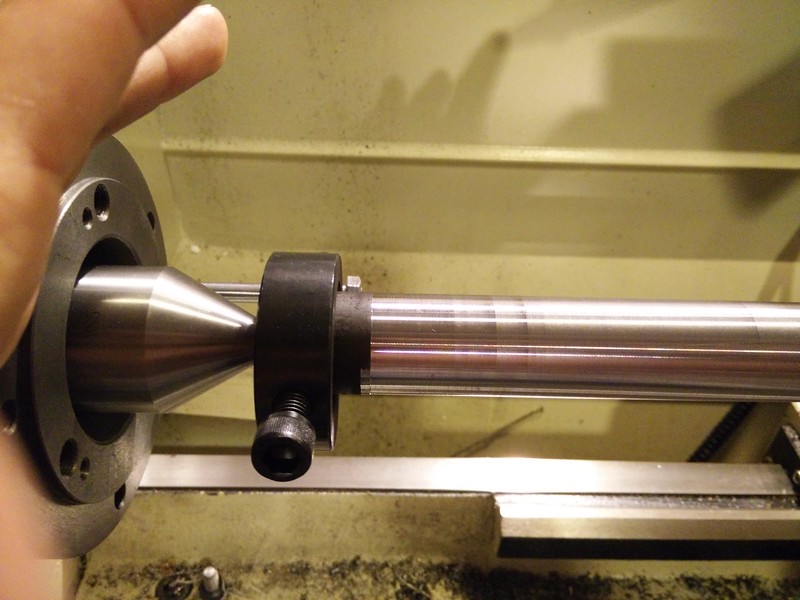
Picture for comparison:

UPDATE: Problem solved for the DT Swiss option, if I end up going that route; the hub end spline apparently is a thread-in deal; Broaching would be a PITA, but threading is relatively easy.
UPDATE 2: Made a tool to disassemble the hub, and it's a style you really do NOT want to try boring out much... I might be able to get away with 1-2mm, (About all I want honestly,) but I can't guarantee it won't affect the strength of the hub going forward. I'll take some pictures tomorrow and consult a fellow machinist in the morning, watch for another update Monday.
UPDATE 3:
Cassette A: is SUPER FREAKIN' HARD STEEL!!! Like I don't even KNOW what this crap is made of, but carbide BARELY cuts it! I enlarged the bore from 3.4mm to 3.5mm and that's about as far as I've been able to remove. Tried an adjustable reamer with steel blades and the cutting surfaces rounded off.
Pics of cassette design taken apart:


Really starting to think Plan B is the better option:

UPDATE 4:
So I tried boring again, and it turns out that the cassette just had a massively hard surface layer. Unfortunately, my steel-shanked carbide boring bar swayed back into place once it cut through this, and over-bored by 0.6mm more than I wanted. Sure is gonna be iffy, but I think I can probably live with it for the moment. My 6-foot bar of 4340 arrived as well, so I may start roughing out the shaft tonight. As always, keeping y'all posted!
UPDATE 5:
Turns out I'm a complete derp, and the bearing I wanted to put in was 15mm; I'd targetted 14mm for shaft diameter. Just threw the hub back in the lathe and got it bored to 15.15mm exactly. Should avoid contact with the shaft, and it'll let me run 15mm all the way out to the threads. The original shaft only goes to 13mm in comparison. This should actually be stronger than a non-cassette wheel when I'm done!

Bearing inner is 15mm exactly, bore is 0.15mm larger.

Not much meat left on this guy, but really it shouldn't exert a lot of load, and I'm going to back it up with a tubed-nut to retain the bearing(s) anyway.
Derp #2: I lost one of the balls from the cassette. It shot off and has attained freedom where all small highly mobile parts such as springs and ball bearings hide in my shop. Now I'll have to measure the bearing diameter and order a pack of them; might as well anyway so I have spares. What's a good grease to use in cassettes? I'll probably want to drop the whole thing in my ultrasonic and re-grease just in case any of the cutting chips got inside the bearing surfaces anyway.
Update - 2015/09/15 - Popped the motor open today, looks very clean; in fact, maybe cleaner than Neptronix's motor.

...Aside from this random piece of copper wire....

One of the halls doesn't look perfectly aligned...

The rest are OK, though not as far out as they could be. There's slots for halls on the other side of the stator as well; I may order a few and swap out all of them with new ones aligned correctly; we shall see...

Also note the temp sensor poking out from under the windings... Hey there little guy!
Pulled the freewheel cover and magnets with this arrangement. Single-speed freewheel is a beast, I doubt it was damaged in the slightest from the (mis)treatment.

There was ZERO gap between any of my magnets, meaning they cut the right diameter for my motor; Neptronix's had had an issue where there was a gap, this just means that his can was fractionally larger in diameter than was optimal.
Only issue I see is one of my magnets is missing a tiny corner:

Oddly, the vanes were machined down on the ends on the freewheel cover. I have no idea why; I don't think there's anything even remotely near that they can hit...

I turned down a water pipe coupler and cut a slot in it to avoid the cable bundle; should let me (eventually) press the bearing out of the brake-side cover without mangling the wire bundles.

Makes enough contact with the inner race of the bearing that it should allow me to slide-hammer or press it out; my next challenge is figuring out how to support the darn side cover with enough surface area that it A: doesn't distort, and B: pops the bearing. Seems like either they pressed in the bearings with a crap-ton of force, or they used some sort of glue or locktite.
October 2015: Got 'er removed; turns out that the shaft necks down enough to allow the bearing to pop and be removed without damaging the wire bundle. It's tight, but the cable doesn't even kink. Hardest part of the whole process was de-pinning the hall connector to remove the side cover, then re-pinning in the same configuration afterward.


(I've seen TONS of examples that show the wire color scheme may or may not match between motors; Especially with the temp sensor wire color. As such, use mine as reference, but don't take it for granted that it's correct for your motor).
Here it is separated:

Here's the comparison of the two styles of shaft:


And here's the three parts I'll be installing:

Brake rotor side has two different designs; one has a round profile, one has gussets:

I like the fully round version as my brake rotor mounts perfectly on it:

The gusset version has protrusions that exceed the diameter of the cut-out in the carrier on my rotor. I could always simply cut them down at the contact area if I really needed to, but it's still a consideration to make when speccing out parts. I suspect Leafbike used the round-mount design for my build because it supported a larger diameter shaft for the 3mm² phase wires with larger diameter bearings; I'll confirm this later.
Lastly, here's my first (terrible) cut of 4340:

Lathe cuts just fine, but I'm going to wait for a new wedge-type BXA tool post to arrive before I make any further cuts. I suspect my piston type is allowing a bit of "give" in my tooling. Either way, this stuff work-hardens a lot, so I'm not expecting totally beautiful results for a while. I'll likely draw-file to final diameter. Further, this is the first center-to-center cutting I've done on this lathe, and I've had to do a lot of adjustments to get it to cut true. I fully expect more to be required before everything is perfectly accurate. Good example: Left side is wider than the right from this last cut:

So I ordered a Sabvoton SSC 048150 off aliexpress. Shipped promptly, price was right, I think I got more than my money's worth honestly. Only downside is the hall plug was broken when it arrived.  (More on this later).

(Let me tell you, it's bigger than the pictures make it appear).
First off: the base plate is an effing HUGE heat-sink. Like 3/8" thick at a minimum.
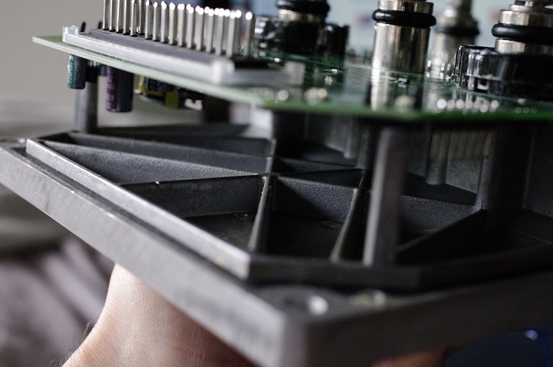
Second, turns out it's a 24 4110 FET design with 100V-rated capacitors. (0.5F per phase).
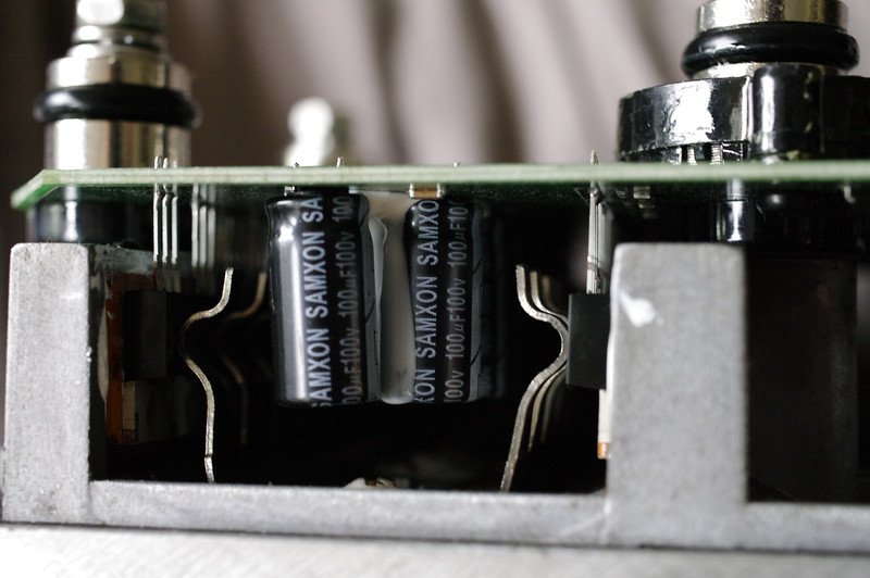
I'm told layout is almost identical to a Sevcon Gen4.
So on to the broken connector. I couldn't readily find the white 6-pin hall connector plugs on ebay, so I got black ones instead. Warning: The housings are different as are the pins. If you convert, you have to snip off the wires at the pins and re-crimp.
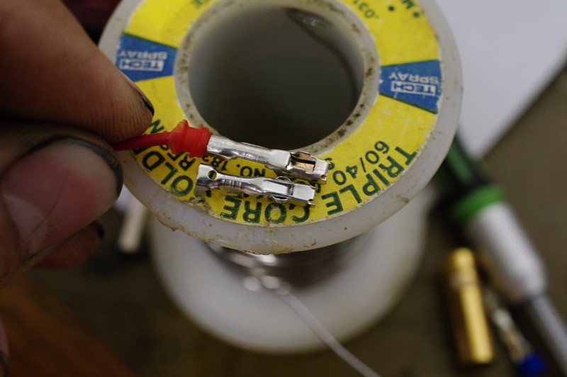
(Top: "White" connector. Bottom: "Black" connector. Note the keying "wings" are different between the two in how they engage with the housings).
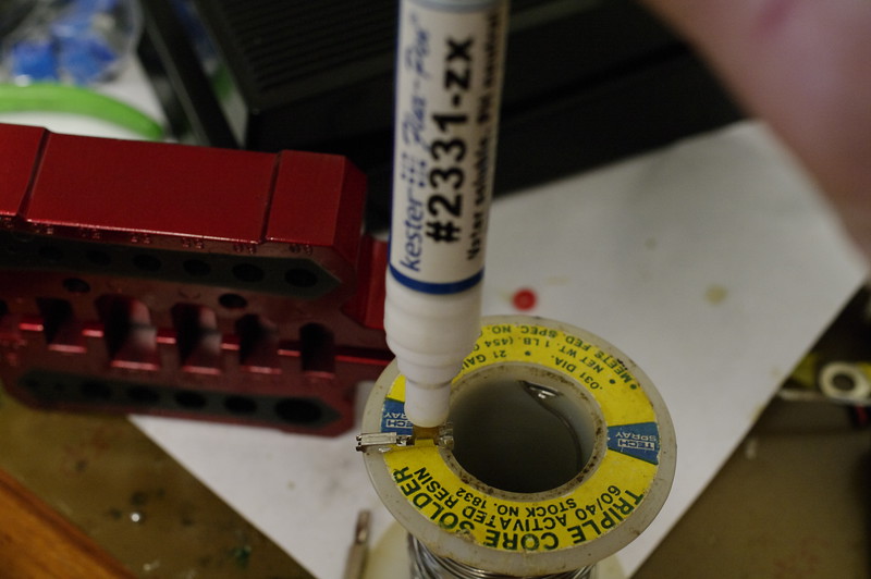
Since my crimper wasn't doing perfect crimps, I opted to crimp then solder. I know this isn't ideal, but it's what I chose to do.
First up: flux the crimp section where the wire will go.
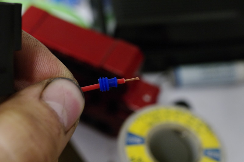
Next, we insert the wire into one of the rubber glands, narrow side toward the wire's end, and strip back insulation to an appropriate length to cover the area the center "wings" cover in the crimp.
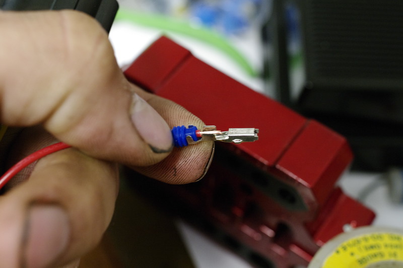
Slide up the rubber gland to the end of the insulation like so, and engage the outer "wings" in the groove in the glad; the whole thing gets crimped together so the glad doesn't slide down the wire. Pretty slick design if you ask me.
Use a high-quality crimper if you're going to do this. I got mine off ebay, it's paid for itself many times over.
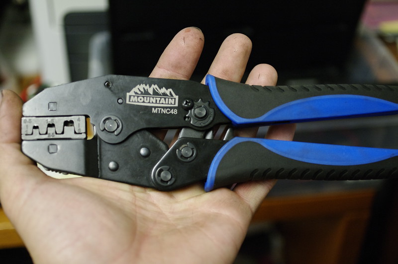
Comes with several quick-change jaws, and you can get more if you ever need to do other cable types. I'm using the "C" jaws in this case; they are the most appropriate for these connectors.
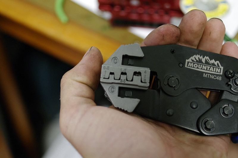
Also make sure you adjust the tension adjustment. My first two pin attempts failed because I was off by one position on my tension adjustment.
The next step is somewhat tricky. It ideally would involve a third hand you don't really have, so I closed down the crimper with my leg while holding the crimp and wire together.
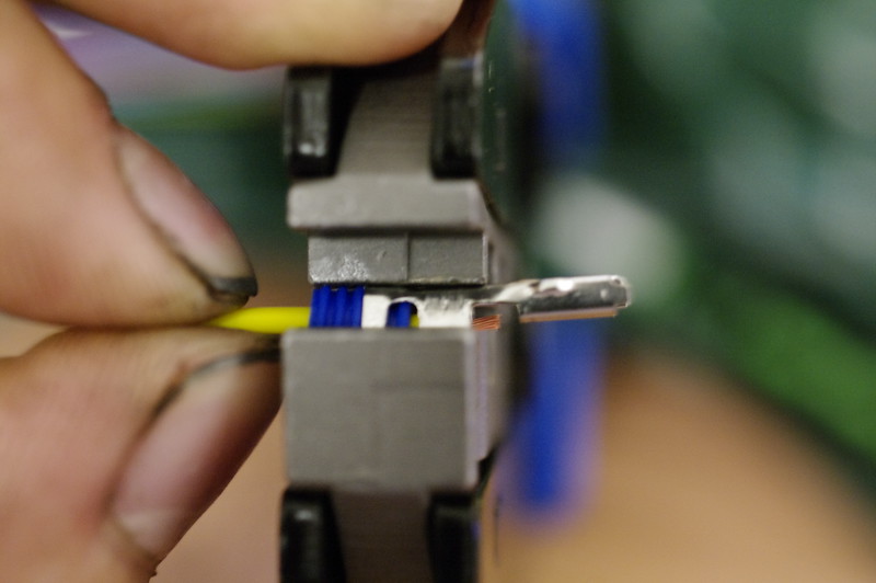
Close it down enough to hold things together and make sure it's aligned:
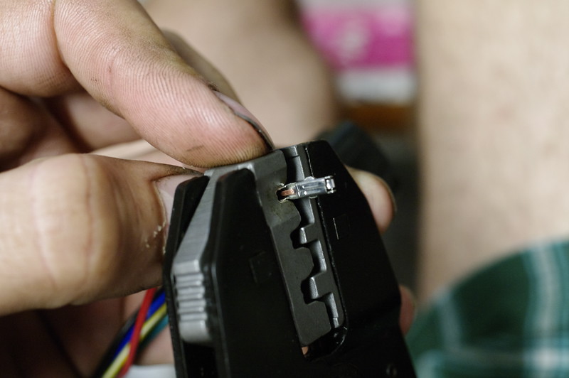
As I'm OCD, I took a tiny screwdriver and tamped down the wire to the bottom of the crimp shell. Not needed, but I did it anyway. If nothing else it spreads the wires out evenly in the shell at the bottom.
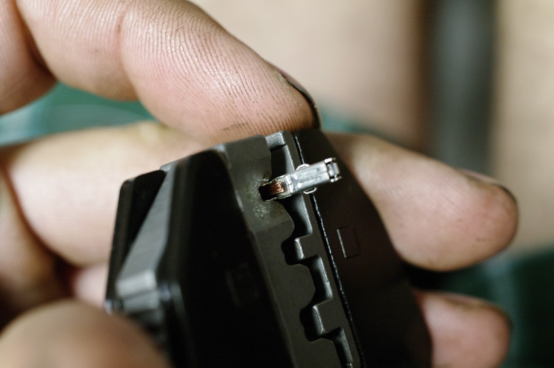
Now you can't go slow on the next bit; the crimps won't form as well as if you do it quick. Squeeze down the crimper until it stops and the ratchet releases. If done right, it should look like this before you release:
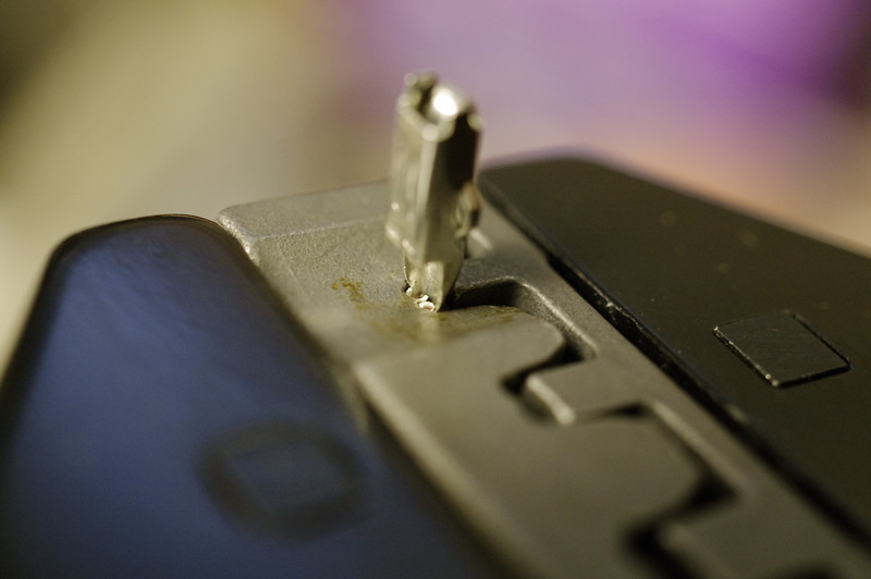
And like this when released:
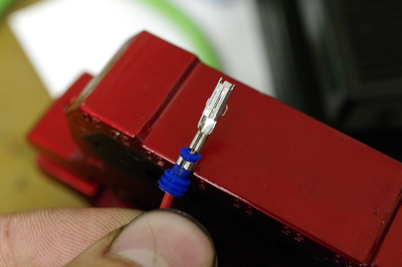
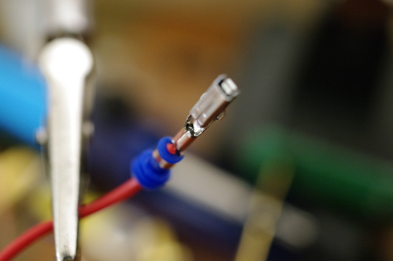
As I had problems with wires still pulling out, (turns out it was my tension adjustment being off,) I also put a tiny dab of solder down inside each crimp. Be quick about it, these aren't designed to be soldered and the plating will oxidize very quickly when exposed to heat.
At this point push the pin into the housing.
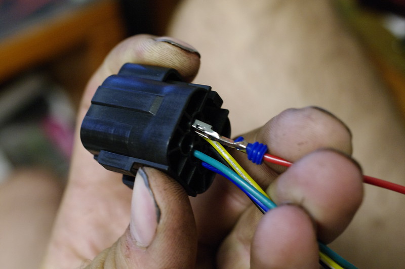
The gland needs a bit of fiddling to align in the hole.
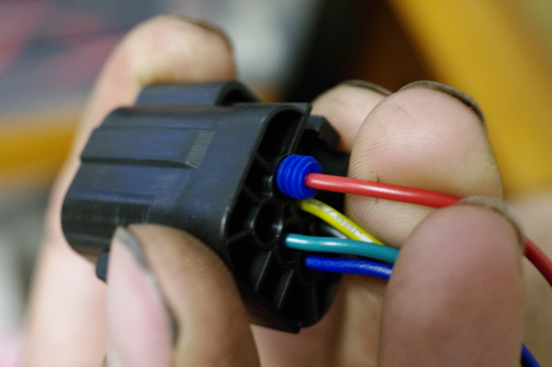
Make sure it fits correctly before pushing the rest of the way in.
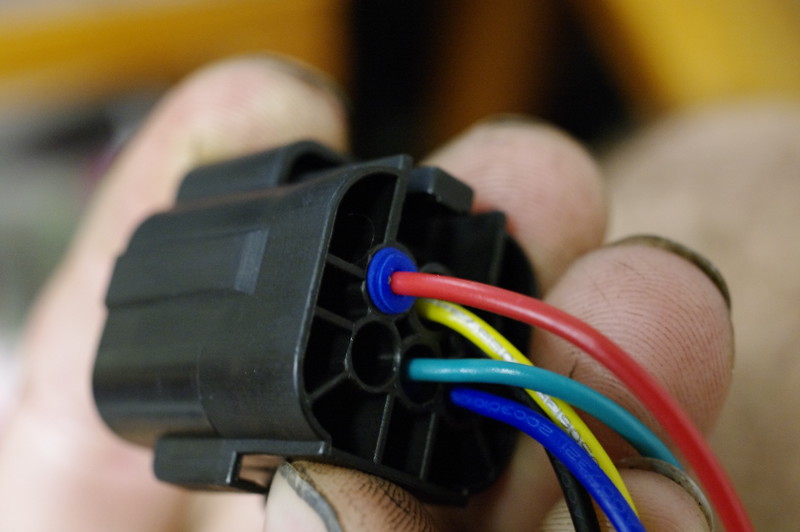
(Hard to demonstrate while holding a camera, but you get the idea). Push the pin the rest of the way in until it bottoms out:
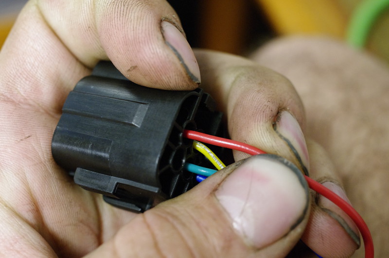
Don't worry, the pins can't be pushed all the way through. Just make sure they are all the way up front. There's a locking tab that engages each contact that should click down into place when installed correctly.
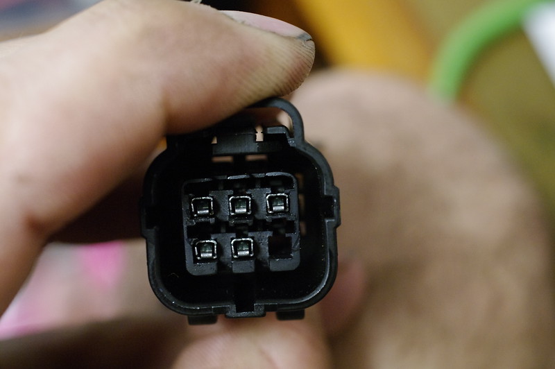
Once all the pins are in, grab the rubber seal and stick it into the female-pinned connector:
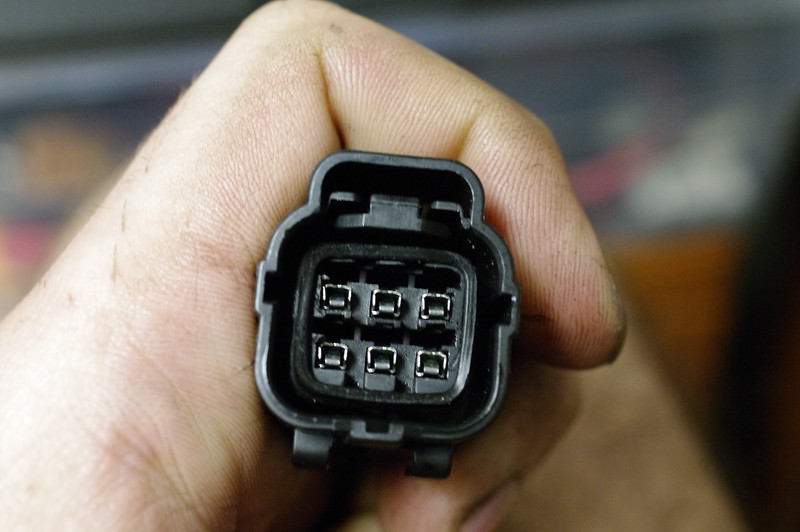
Push it all the way down carefully with something small enough to fit inside but not sharp enough to cut or pierce the seal:
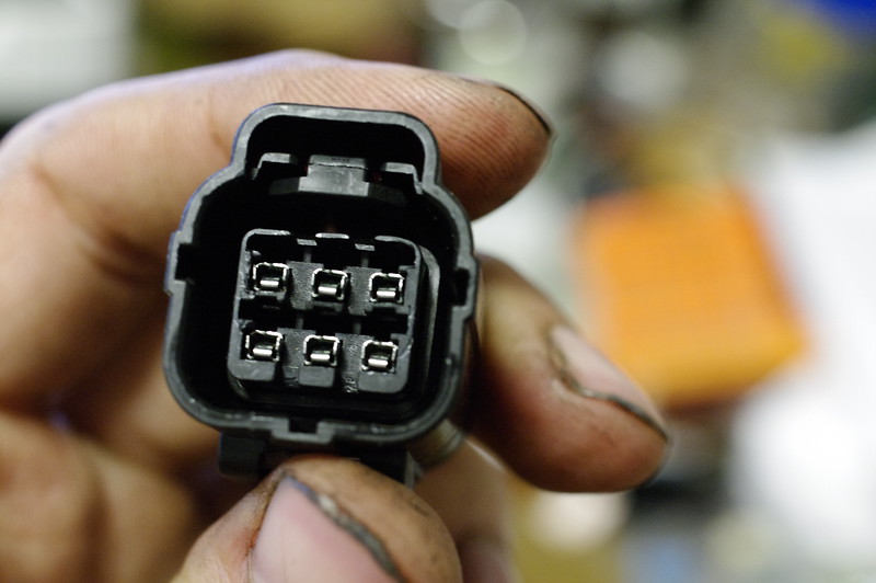
The yellow cover keeps the locking tabs from raising up, effectively double-locking the pins in place. It just snaps in, like so.
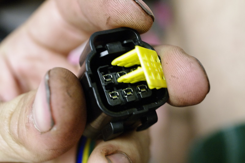
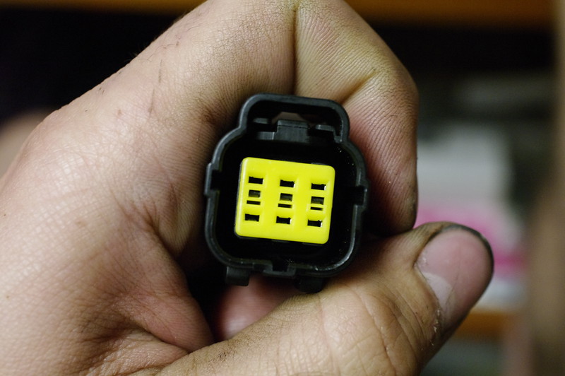
All done!
I'll be replacing all connectors on my bike with these; I know it's overkill in many cases, but I live in Oregon, where moisture is constant; I'd rather not have to worry about crap getting into the connections or corrosion occurring quickly.

(Let me tell you, it's bigger than the pictures make it appear).
First off: the base plate is an effing HUGE heat-sink. Like 3/8" thick at a minimum.

Second, turns out it's a 24 4110 FET design with 100V-rated capacitors. (0.5F per phase).

I'm told layout is almost identical to a Sevcon Gen4.
So on to the broken connector. I couldn't readily find the white 6-pin hall connector plugs on ebay, so I got black ones instead. Warning: The housings are different as are the pins. If you convert, you have to snip off the wires at the pins and re-crimp.

(Top: "White" connector. Bottom: "Black" connector. Note the keying "wings" are different between the two in how they engage with the housings).
Since my crimper wasn't doing perfect crimps, I opted to crimp then solder. I know this isn't ideal, but it's what I chose to do.
First up: flux the crimp section where the wire will go.

Next, we insert the wire into one of the rubber glands, narrow side toward the wire's end, and strip back insulation to an appropriate length to cover the area the center "wings" cover in the crimp.

Slide up the rubber gland to the end of the insulation like so, and engage the outer "wings" in the groove in the glad; the whole thing gets crimped together so the glad doesn't slide down the wire. Pretty slick design if you ask me.

Use a high-quality crimper if you're going to do this. I got mine off ebay, it's paid for itself many times over.

Comes with several quick-change jaws, and you can get more if you ever need to do other cable types. I'm using the "C" jaws in this case; they are the most appropriate for these connectors.

Also make sure you adjust the tension adjustment. My first two pin attempts failed because I was off by one position on my tension adjustment.
The next step is somewhat tricky. It ideally would involve a third hand you don't really have, so I closed down the crimper with my leg while holding the crimp and wire together.

Close it down enough to hold things together and make sure it's aligned:

As I'm OCD, I took a tiny screwdriver and tamped down the wire to the bottom of the crimp shell. Not needed, but I did it anyway. If nothing else it spreads the wires out evenly in the shell at the bottom.

Now you can't go slow on the next bit; the crimps won't form as well as if you do it quick. Squeeze down the crimper until it stops and the ratchet releases. If done right, it should look like this before you release:

And like this when released:

As I had problems with wires still pulling out, (turns out it was my tension adjustment being off,) I also put a tiny dab of solder down inside each crimp. Be quick about it, these aren't designed to be soldered and the plating will oxidize very quickly when exposed to heat.

At this point push the pin into the housing.

The gland needs a bit of fiddling to align in the hole.

Make sure it fits correctly before pushing the rest of the way in.

(Hard to demonstrate while holding a camera, but you get the idea). Push the pin the rest of the way in until it bottoms out:

Don't worry, the pins can't be pushed all the way through. Just make sure they are all the way up front. There's a locking tab that engages each contact that should click down into place when installed correctly.

Once all the pins are in, grab the rubber seal and stick it into the female-pinned connector:

Push it all the way down carefully with something small enough to fit inside but not sharp enough to cut or pierce the seal:

The yellow cover keeps the locking tabs from raising up, effectively double-locking the pins in place. It just snaps in, like so.


All done!
I'll be replacing all connectors on my bike with these; I know it's overkill in many cases, but I live in Oregon, where moisture is constant; I'd rather not have to worry about crap getting into the connections or corrosion occurring quickly.
Been a while since I've updated this post... Been busy stripping down and reassembling both of my milling machines and my bandsaw to fix a bunch of issues I've had with them all. In the process nearly lost one finger and sliced my hand open pretty good. Anyway, I have an update!
I made an adapter block from some spare aluminum that joins a linear pressure transducer to a motorcycle brake handle. The fun part about this design is the block used has an air pocket at the top to allow for some compression of the handle. Since the whole thing isn't driving anything, it would normally be VERY hard and just lock up after pressing slightly. The air pocket keeps the hydraulic system from being completely "bled" of air, which gives the whole system some give. Feels very similar to actually activating hydraulic brakes and getting the feedback of pushing on a brake rotor; the resistance is pretty smoothly progressive and my transducer looks sensitive enough to register very minute changes in handle pull.
Hardest part of this project was finding a banjo bolt that was long enough to fit through the block and still be able to screw in. To top it off, the brake handle I bought (cheapo option on ebay,) used an M10x1.25 pitch banjo bolt. Normal M10 threads are either 1.0 or 1.5 thread pitch, not 1.25; Ended up buying a bolt at a specialty hardware store and cross-drilling, then boring to make my own "custom" banjo.
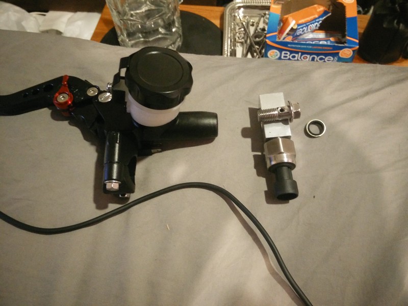
As you can see, the "stock" bolt for this handle was almost too short to even fit through the aluminum block.
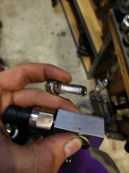
Finished "banjo" bolt.
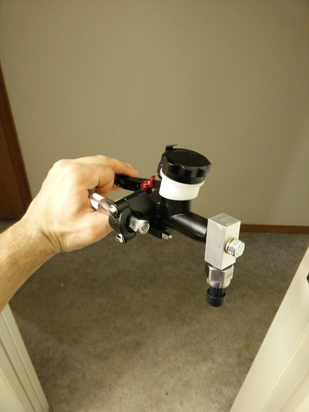
Mounted, tightened, filled with DOT4, bled, and pressure tested.
The block is drilled to within 5mm of the top through length-wise in the center, I think I used a 9mm drill bit, if anyone is curious. Block dimensions are ~20mm*20mm*40mm.
Among other things, this handle generates over 200 PSI when squeezed hard. This is not necessarily good, as it tops out the range of my 0-200 PSI transducer. May have to order a 300 or 500 PSI transducer to get "full" range readings including "panic stop" pull force. This will eventually be incorporated into an input for the Sabvoton variable regen brake input line.
I made an adapter block from some spare aluminum that joins a linear pressure transducer to a motorcycle brake handle. The fun part about this design is the block used has an air pocket at the top to allow for some compression of the handle. Since the whole thing isn't driving anything, it would normally be VERY hard and just lock up after pressing slightly. The air pocket keeps the hydraulic system from being completely "bled" of air, which gives the whole system some give. Feels very similar to actually activating hydraulic brakes and getting the feedback of pushing on a brake rotor; the resistance is pretty smoothly progressive and my transducer looks sensitive enough to register very minute changes in handle pull.
Hardest part of this project was finding a banjo bolt that was long enough to fit through the block and still be able to screw in. To top it off, the brake handle I bought (cheapo option on ebay,) used an M10x1.25 pitch banjo bolt. Normal M10 threads are either 1.0 or 1.5 thread pitch, not 1.25; Ended up buying a bolt at a specialty hardware store and cross-drilling, then boring to make my own "custom" banjo.

As you can see, the "stock" bolt for this handle was almost too short to even fit through the aluminum block.

Finished "banjo" bolt.

Mounted, tightened, filled with DOT4, bled, and pressure tested.
The block is drilled to within 5mm of the top through length-wise in the center, I think I used a 9mm drill bit, if anyone is curious. Block dimensions are ~20mm*20mm*40mm.
Among other things, this handle generates over 200 PSI when squeezed hard. This is not necessarily good, as it tops out the range of my 0-200 PSI transducer. May have to order a 300 or 500 PSI transducer to get "full" range readings including "panic stop" pull force. This will eventually be incorporated into an input for the Sabvoton variable regen brake input line.
BACK TO THE DRAWING BOARD (April 2018)
So I got a Chinese "Tank" ebike frame. It's got a couple issues, and it's REAL heavy, but they were quite easy to deal with. First off, the swing arm being on a rubber bushing is TERRIBLE. I had to press it out, turn down some tube to fit the real odd sized bore of the frame, bore the tube to admit a pair of bearings, and then there's an issue of the large amount of space between swing arm and frame... For that, I ended up adding washers, and then for good measure drilled out the frame slightly and added a pair of spacers like so:
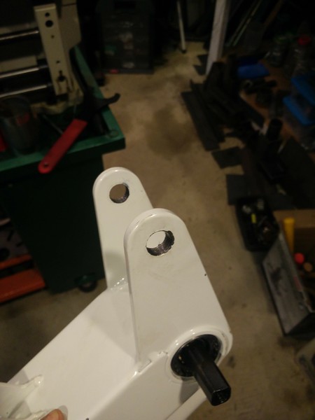
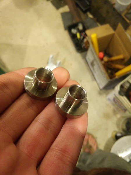
The whole thing bolts together super nice and easy, looks pretty, and swings with almost zero resistance now:
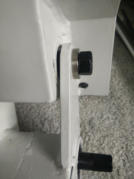


The whole thing bolts together super nice and easy, looks pretty, and swings with almost zero resistance now:

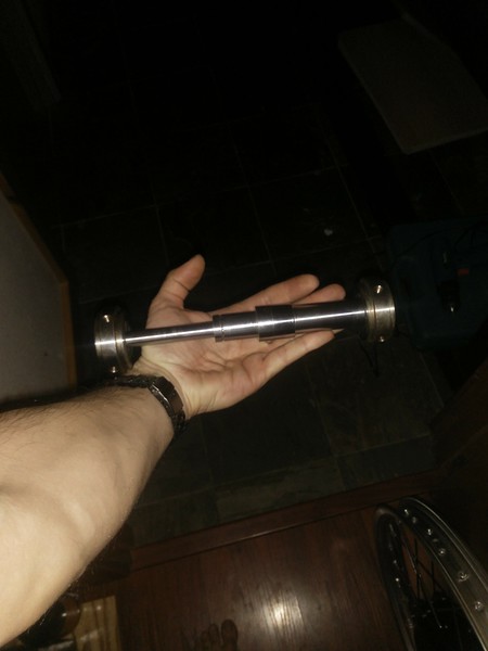
I hammered this one out in an hour, since I had to cut a second new shaft from raw 4340 stock:
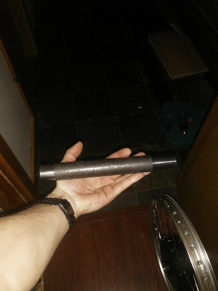
...And done:
All to "spec" this time:
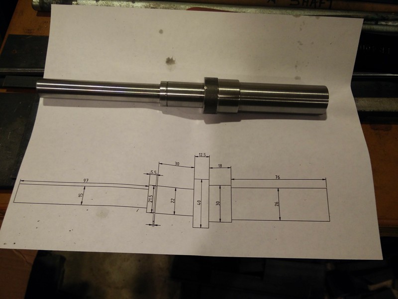
Keyways were cut and slots on either side cut to fit tightly in the dropouts of the new frame. No pictures (yet) for this one, as I haven't pulled the motor apart to finish the job yet. When I do, I'll update this section.

...And done:

All to "spec" this time:

Keyways were cut and slots on either side cut to fit tightly in the dropouts of the new frame. No pictures (yet) for this one, as I haven't pulled the motor apart to finish the job yet. When I do, I'll update this section.
I'll post these in a day or two; lots of pictures for this one.
Before...
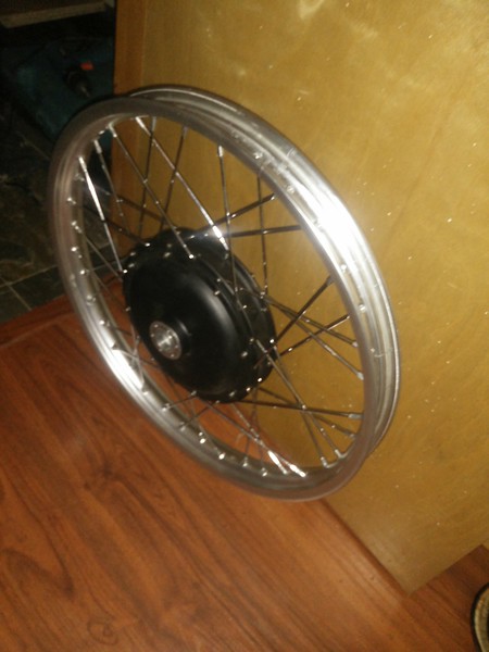
Most of the way there:
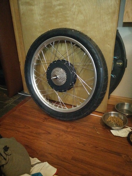
You can see that the shaft fits correctly, bearings are tight fit, but about the same as "stock" insofar as that the side cover bolts can pull the bearing onto the shaft, and yes, that is a 9-speed cassette mounted to a Leafbike 1500W motor. Pretty sure I now have the only such configuration in the world. 8)

Most of the way there:

You can see that the shaft fits correctly, bearings are tight fit, but about the same as "stock" insofar as that the side cover bolts can pull the bearing onto the shaft, and yes, that is a 9-speed cassette mounted to a Leafbike 1500W motor. Pretty sure I now have the only such configuration in the world. 8)
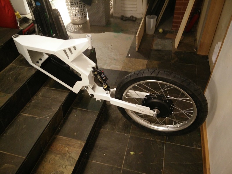
Here's where it all comes together. After cutting the slots in the shaft ends and test-fitting to the swing-arm, I threw the (yet unwired but otherwise functionally complete) hubmotor with new shaft on the swing-arm, and mounted it to the frame:
Then I added my Marzocci 888 fork, with the hand-laced 21" motorcycle rim/tire, and Denzel oversized 20mm through-axle hub with oversized spoke holes (This was a really nice hub for the front wheel build).
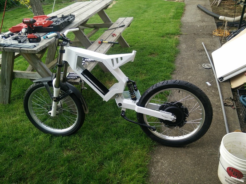
Both wheels are 21" alloy motorcycle rims. (21x1.6" IIRC) You can also see the hubsink mounted to the leafbike motor. Motor is as-yet not wired, will update previous motor/wheel section once I get to that...

Then I added my Marzocci 888 fork, with the hand-laced 21" motorcycle rim/tire, and Denzel oversized 20mm through-axle hub with oversized spoke holes (This was a really nice hub for the front wheel build).

Both wheels are 21" alloy motorcycle rims. (21x1.6" IIRC) You can also see the hubsink mounted to the leafbike motor. Motor is as-yet not wired, will update previous motor/wheel section once I get to that...
MAY 2019:
And this is where I leave you once again hanging... The project has once again stalled due to funds, as I need a decent battery for this rig. Once I budget for that and purchase the packs, I'll pull the hubmotor off the frame, take photos, wire up phase/hall wires, close it up, add Statorade, (Is it trademarked? Do I need to put the TM sign after it?), mount the controller, wire up the controls, and hopefully not kill myself the first time I get on this thing and twist the throttle.


